Section 10 Transferring Data 10-1 Transferring Data to the PT
NS-Designer Operation Manual
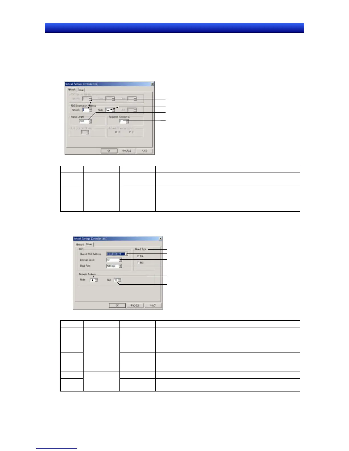
Controller Link Communications
1. Make the following settings on the Network Tab Page.
1
2
3
4
No. Field Item Details
1 Network Set the network address of the Controller Link network to which
the PT is connected.
2
FINS Destina-
tion Address
Node Set the node address of the PT.
3 Frame length - Set the maximum frame length. Use the default setting.
4 Response
Timeout
- Set the response timeout time. Increase the time only when there
are frequent communications errors.
2. Make the following settings on the Driver Tab Page.
1
2
3
5
4
6
No. Field Item Details
1 Shared RAM
Address
Set to the same value as the DIP switch on the Controller Link
Support Board.
2 Interrupt Level Set to the same value as the jumper pins on the Controller Link
Support Board.
3
NSB
Baud Rate Set the baud rate to 500 Kbps, 1 Mbps, or 2 Mbps.
4 Board Type - Set the Controller Link Support Board type to ISA for an ISA
Board or to PCI for a PCI Board.
5 Node Set the local node address of the Controller Link Support Board.
6
Network Ad-
dress
Unit Set the unit number of the Controller Link Support Board be-
tween 16 and 31.
10-17