76
Setting the NV Configuration from the NV-Designer Section 6-2
Operations Using the
System Memory
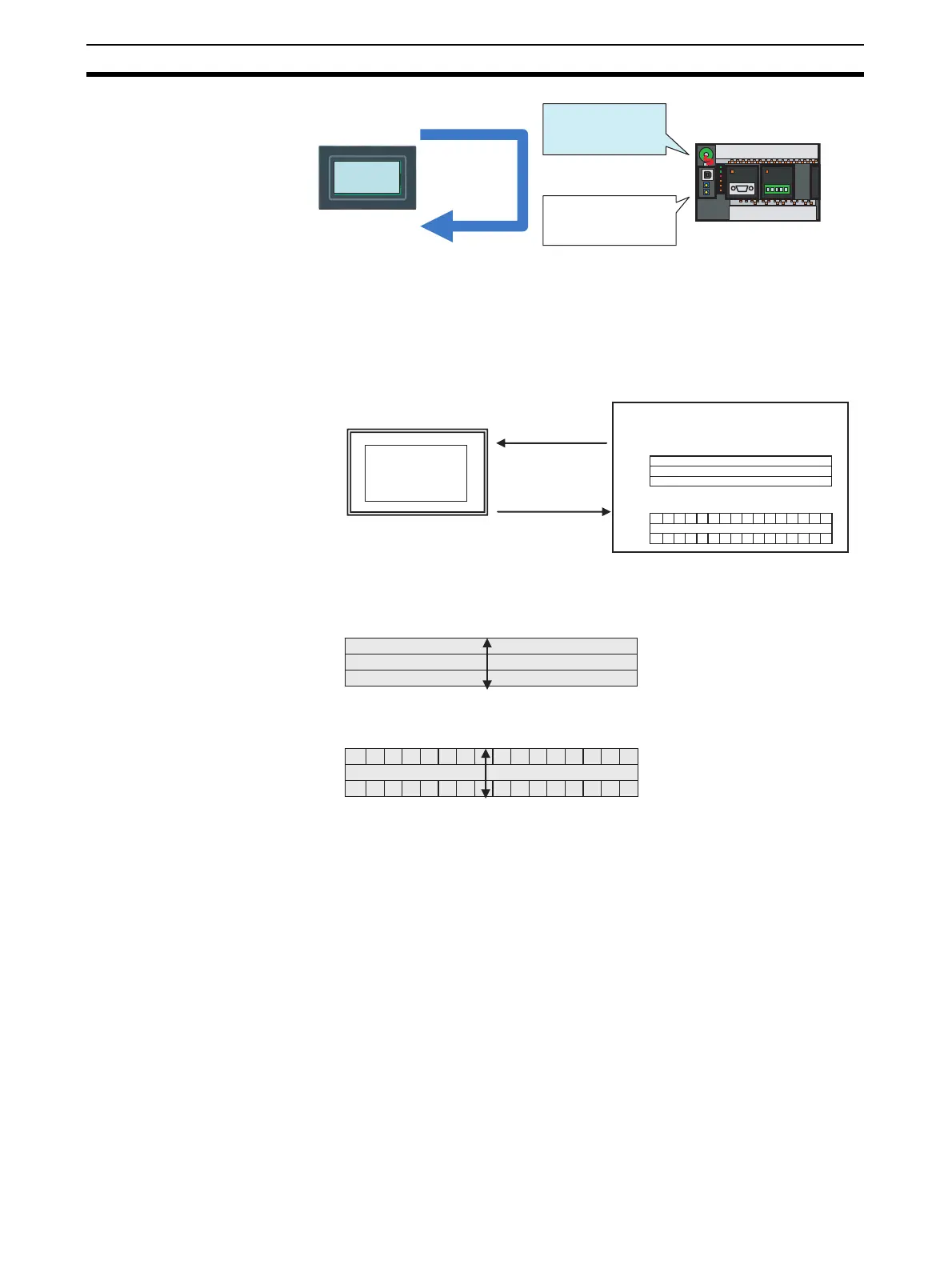
The following parameters can be specified and monitored from the system
memory.
• Specify: Displayed screen number, backlight color, backlight ON/flashing.
• Monitor: Displayed screen number, data being input, battery backup
error, low battery.
Contents of System
Memory
Three words are allocated for the Word Area and three words are allocated for
the Bit Area.
The following words are set as the system memory by default.
Word Area: D0 to D2
Bit Area: 0 to 2
The first address can be changed in the NV Configuration from the NV-
Designer.
PT
Continuous
communications
PLC
System Memory
Specifies the screen
number and backlight
color.
PLC internal memory
Communications
Addresses for Parts
An address is specified
for each part.
PLC
PT
Specification
Screen number,
backlight color, etc.
Monitor
Displayed screen
number, input data, etc.
System memory
Word Area
Screen Number from PLC
Not used.
Current Screen Number
Bit Area
Not used.
N
N+1
N+2
N
N+1
N+2
Word Area
N
N+1
N+2
N
N+1
N+2
Three consecutive words
Bit Area
Three consecutive words
 Loading...


