78
Setting the NV Configuration from the NV-Designer Section 6-2
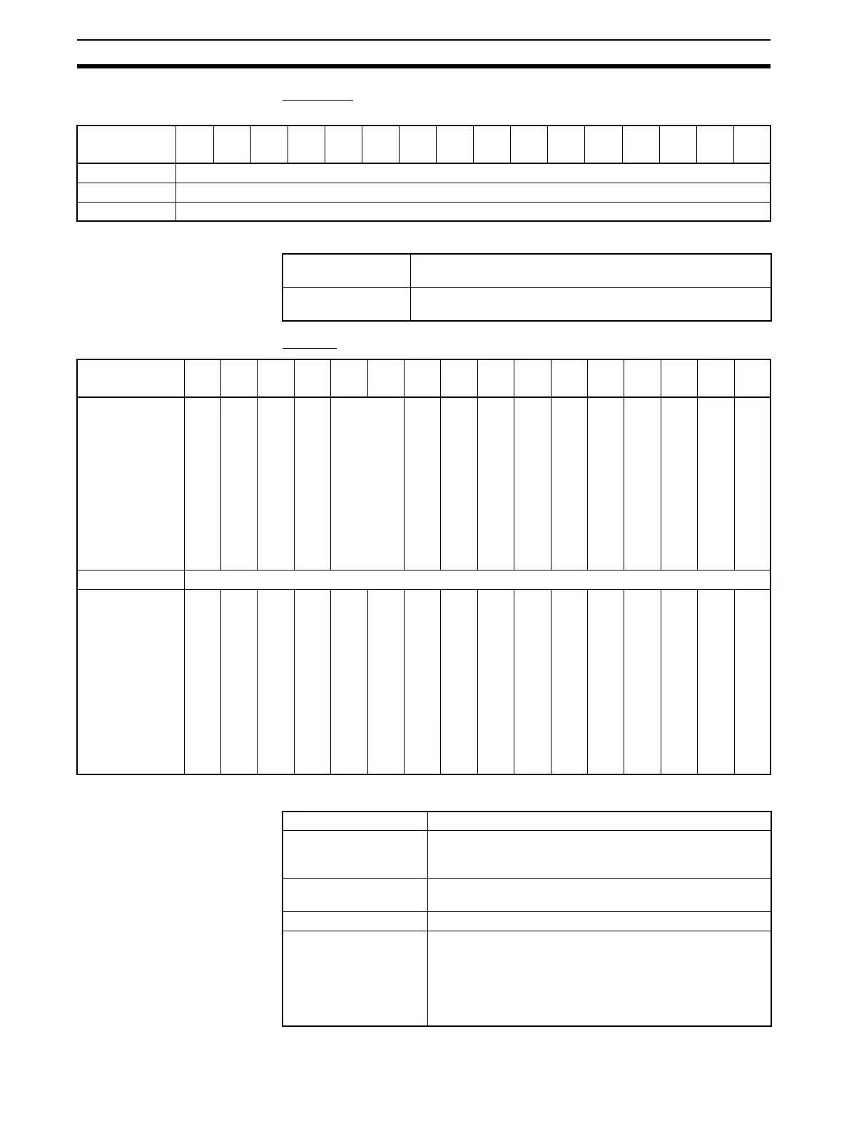
NV4W/NV3Q System
Memory Map
Word Area
Word Area Description
Bit Area
Bit Area Description
Bits
Word
1514131211109876543210
N + 0 Screen Number from PLC (PLC tells the NV4W/NV3Q to using this number.)
N + 1 Do not use.
N + 2 Current Screen Number (PLC reads this number from the NV4W/NV3Q.)
Screen Number from
PLC
This word contains the screen number specified by the PLC
for the NV4W/NV3Q to display in hexadecimal.
Current Screen
Number
This word contains the number in hexadecimal of the screen
currently displayed on the NV4W/NV3Q.
Bits
Word
1514131211109876543210
N + 0
Buzzer
Screen Display Bit
Backlight Control Enable Bit
Backlight ON/Flash Bit
Backlight color
Key Press Sound Disable Bit
N + 1 Do not use.
N + 2
Password Change Screen Flag
Login Screen Flag
Battery Low Flag
Battery Backup Error Flag
Data Entry Flag
Buzzer Turn ON this bit to turn ON the buzzer.
Screen Display Bit Turn ON this bit to make the PT display the screen speci-
fied by the PLC. (This bit is effective only when it changes
from OFF to ON.)
Backlight Control
Enable Bit
Turn ON this bit to enable controlling the backlight (flashing
and color).
Backlight ON/Flash Bit OFF: Lit (normal), ON: Flashing
Backlight color NV4W:
00: Not lit, 01: Green (white), 10: Red, 11: Orange (pink)
NV3Q Monochrome:
00: Not lit, 01: White, 10: Red, 11: Pink
NV3Q Color:
00: Not lit, 01: Lit, 10: Lit, 11: Lit