4-44
4-3 Wiring Conforming to EMC Directives
System Design
4
Noise Filters for Servomotor Output
Use noise filters without built-in capacitors on the Servomotor output lines.
Select a noise filter with a rated current at least two times the Servo Drive's continuous output
current.
The following table shows the noise filters that are recommended for Servomotor output.
Note1. Servomotor output lines cannot use the same noise filters for power supplies.
Note2. Typical general-purpose noise filters are made for power supply frequencies of 50/60 Hz. If
these noise filters are connected to the PWM output of the Servo Drive, a very large (about
100 times larger) leakage current will flow through the noise filter's condenser and the Servo
Drive could be damaged.
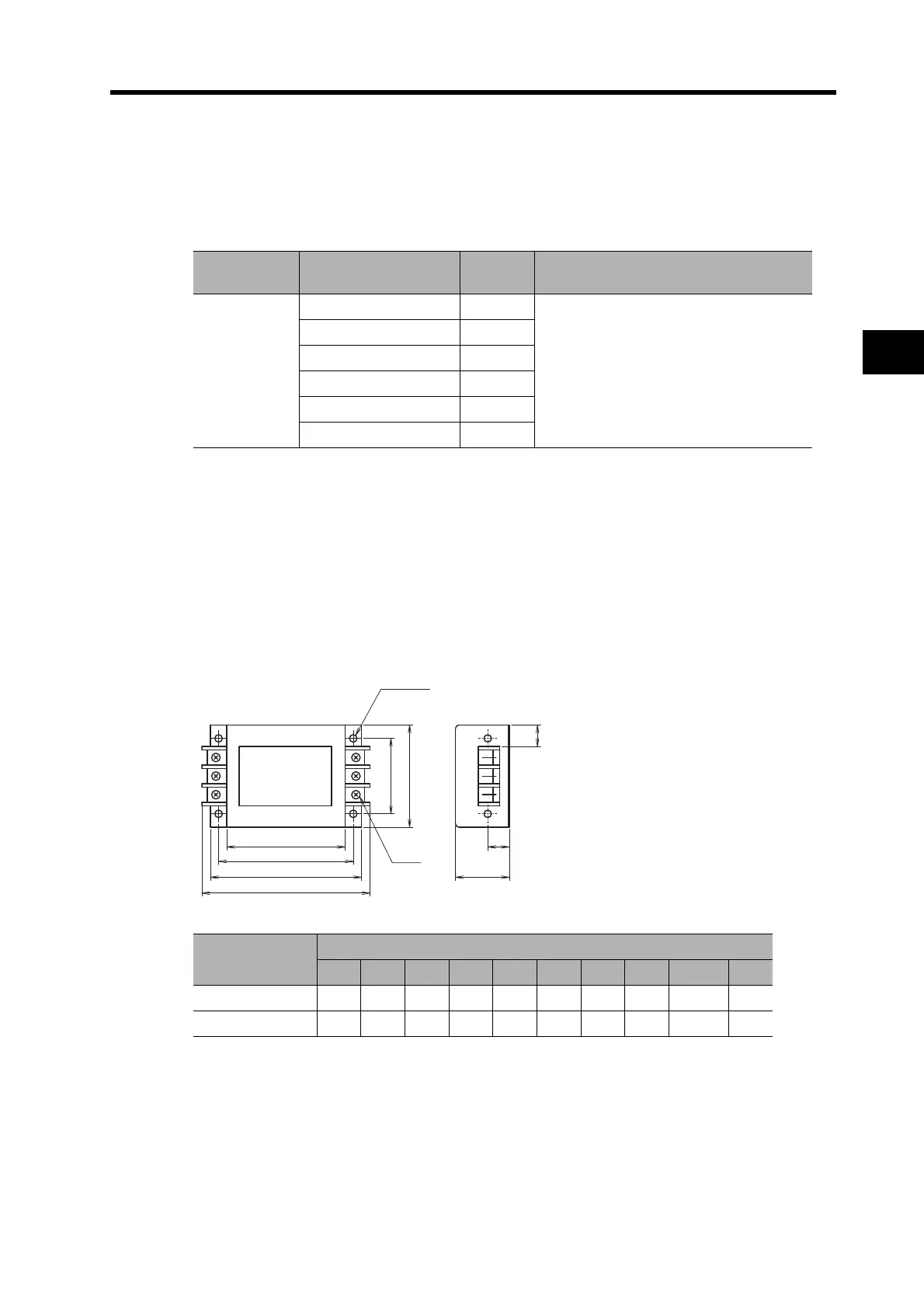
Dimensions
3G3AX-NF001/-NF002
Manufacturer Model
Rated
current
Remarks
OMRON
3G3AX-NF001 6 A
For inverter output
3G3AX-NF002 12 A
3G3AX-NF003 25 A
3G3AX-NF004 50 A
3G3AX-NF005 75 A
3G3AX-NF006 100 A
Model
Dimensions (mm)
A B C E F G H J M P
3G3AX-NF001 140 125 110 70 95 22 50 20 4.5 dia. 156
3G3AX-NF002 160 145 130 80 110 30 70 25 5.5 dia. 176

 Loading...


