4-54
4-4 Regenerative Energy Absorption
System Design
4
R88D-GN75H-ML2
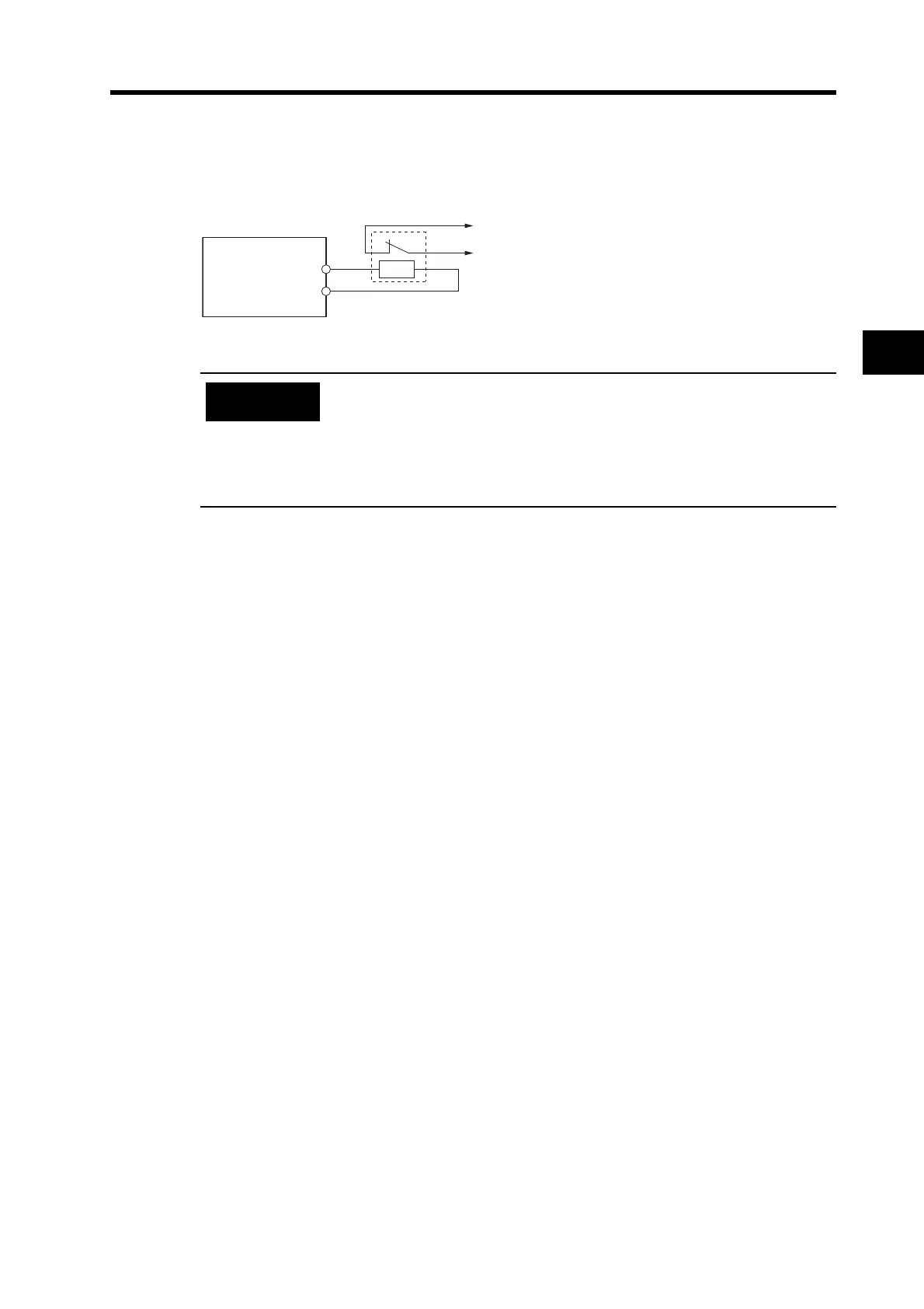
If an External Regeneration Resistor is necessary, connect it between B1 and B2 as shown in the
diagram below.
Connect the thermal switch output so that the main circuit power supply is
shut OFF when the contacts open.
When using multiple External Regeneration Resistors, connect each
thermal switch in series.
The resistor may be damaged by burning, or cause fire if it is used without
setting up a power supply shutoff sequence using the output from the
thermal switch.
Servo Drive
B1
B2
External
Regeneration
Resistor
θ>
Thermal Switch Output
Precautions
for Correct Use

 Loading...


