5-91
5-27 Details on Important Parameters
Operating Functions
5
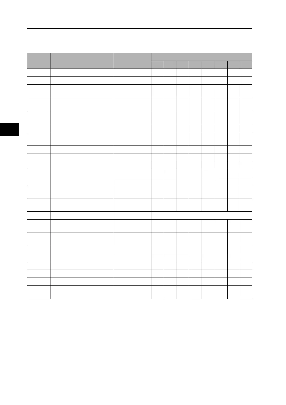
Parameters Pn015, 016, 01A, 030, and 032 to 035 are set to fixed values. The Servo Drive is set to rigidity No.2
as the default value.
*1. The lower limit is set to 10 when using a 17-bit encoder and 25 when using a 2,500-p/r encoder.
*2. The value for a 17-bit absolute encoder. The value for a 2,500-p/r incremental encoder is 25.
*3. The default setting for the Servo Drive is 2 (switching from the network).
Parameter
No.
Parameter name
AT Mode Selection
(Pn021)
AT Machine Rigidity Selection (Pn022)
8 9 A B C D E F
Pn010 Position Loop Gain --- 1350 1620 2060 2510 3050 3770 4490 5570
Pn011 Speed Loop Gain --- 750 900 1150 1400 1700 2100 2500 3100
Pn012
Speed Loop Integration Time
Constant
--- 90 80706050404030
Pn013
Speed Feedback Filter Time
Constant
--- 0000 0 000
Pn014
Torque Command
Filter Time Constant
*1
--- 30 25 20
*2
16
*2
13
*2
11
*2
10
*2
10
*2
Pn015 Speed Feed-forward Amount --- 300 300 300 300 300 300 300 300
Pn016
Feed-forward Filter Time
Constant
--- 50 50 50 50 50 50 50 50
Pn017Reserved --- 0000 0 000
Pn018 Position Loop Gain 2 --- 1570 1820 2410 2930 3560 4400 5240 6490
Pn019 Speed Loop Gain 2 --- 750 900 1150 1400 1700 2100 2100 3100
Pn01A
Speed Loop Integration Time
Constant 2
1, 2, 3, 7 10000100001000010000 10000 100001000010000
4, 5, 6 9999 9999 9999 9999 9999 9999 9999 9999
Pn01B
Speed Feedback Filter Time
Constant 2
--- 0000 0 000
Pn01C
Torque Command Filter Time
Constant 2
*1
--- 30 25 20
*2
16
*2
13
*2
11
*2
10
*2
10
*2
Pn020 Inertia Ratio --- Estimated load inertia ratio
Pn027
Instantaneous Speed
Observer Setting
--- 0000 0 000
Pn030
Gain Switching
Operating Mode Selection
--- 1111 1 111
Pn031 Gain Switch Setting
*3
1 to 6 1010101010 101010
7 0000 0 000
Pn032 Gain Switch Time --- 30 30 30 30 30 30 30 30
Pn033 Gain Switch Level Setting --- 50 50 50 50 50 50 50 50
Pn034 Gain Switch Hysteresis Setting --- 33 33 33 33 33 33 33 33
Pn035
Position Loop Gain Switching
Time
--- 20 20 20 20 20 20 20 20

 Loading...


