7-13
7-3 Normal Mode Autotuning
Adjustment Functions
7
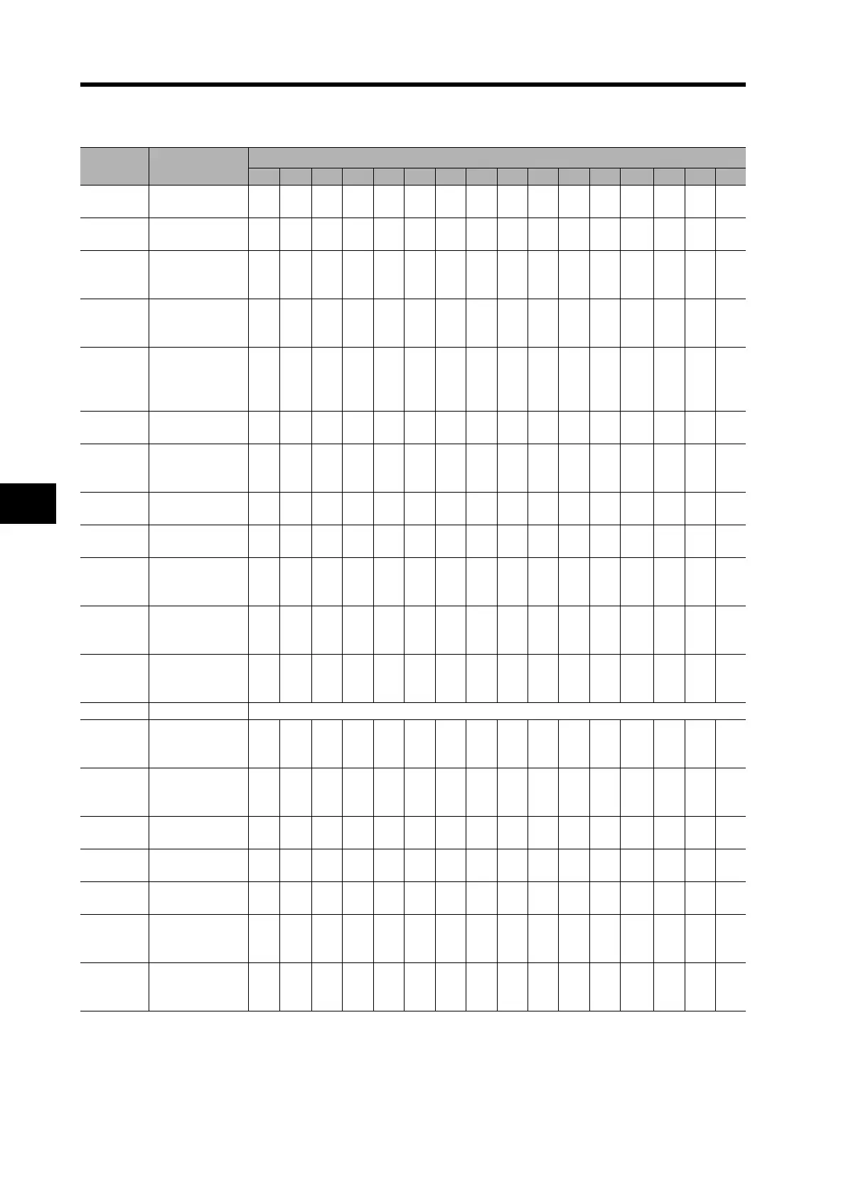
Normal Mode Autotuning (AT) Parameter Tables
*1. The lower limit is set to 10 when using a 17-bit encoder and 25 when using a 2,500-p/r encoder.
*2. The value for a 17-bit absolute encoder. The value for a 2500-p/r incremental encoder is 25.
Parameter
No.
Parameter name
AT Machine Rigidity Selection (Pn022)
0 1 2 3 4 5 6 7 8 9 A B C D E F
Pn010
Position Loop
Gain
120 320 390 480 630 720 900 1080 1350 1620 2060 2510 3050 3770 4490 5570
Pn011
Speed Loop
Gain
90 180 220 270 350 400 500 600 750 900 1150 1400 1700 2100 2500 3100
Pn012
Speed Loop
Integration Time
Constant
620 310 250 210 160 140 120 110 90 80706050404030
Pn013
Speed Feed-
back Filter Time
Constant
0000000000000000
Pn014
Torque
Command
Filter Time
Constant
*1
253 126 103 8465574538 30 25 20
*2
16
*2
13
*2
11
*2
10
*2
10
*2
Pn015
Speed Feed-
forward Amount
300 300 300 300 300 300 300 300 300 300 300 300 300 300 300 300
Pn016
Feed-forward
Filter Time
Constant
50 50 50 50 50 50 50 50 50 50 50 50 50 50 50 50
Pn018
Position Loop
Gain 2
190 380 460 570 730 840 1050 1260 1570 1820 2410 2930 3560 4400 5240 6490
Pn019
Speed Loop
Gain 2
90 180 220 270 350 400 500 600 750 900 1150 1400 1700 2100 2100 3100
Pn01A
Speed Loop
Integration
Time Constant 2
9999 9999 9999 9999 9999 9999 9999 9999 9999 9999 9999 9999 9999 9999 9999 9999
Pn01B
Speed Feed-
back Filter Time
Constant 2
0000000000000000
Pn01C
Torque Com-
mand Filter Time
Constant 2
*1
253 126 103 8465574538 30 25 20
*2
16
*2
13
*2
11
*2
10
*2
10
*2
Pn020 Inertia Ratio Estimated load inertia ratio
Pn027
Instantaneous
Speed Observer
Setting
0000000000000000
Pn030
Gain Switching
Operating Mode
Selection
1111111111111111
Pn031
Gain Switch
Setting
10 10 10 10 10 10 10 10 10 10 10 10 10 10 10 10
Pn032
Gain Switch
Time
30 30 30 30 30 30 30 30 30 30 30 30 30 30 30 30
Pn033
Gain Switch
Level Setting
50 50 50 50 50 50 50 50 50 50 50 50 50 50 50 50
Pn034
Gain Switch
Hysteresis
Setting
33 33 33 33 33 33 33 33 33 33 33 33 33 33 33 33
Pn035
Position Loop
Gain Switching
Time
20 20 20 20 20 20 20 20 20 20 20 20 20 20 20 20

 Loading...


