8-5
8-2 Alarm Table
Troubleshooting
8
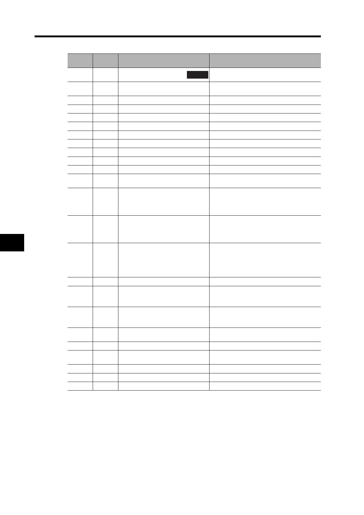
Note The alarm display is in decimal.
For example, if a SYNC command error occurs, "91" will flash on the front panel of the G-
series Servo Drive. The warning code read from the host Position Control Unit (CJ1W-
NC71 or CS1W-NC71) would be 405B.
Alarm
Display
Alarm
Type
Error Detection Function Detection Details and Cause of Error
47 ---
Absolute encoder
status error
The rotation of the absolute encoder is higher
than the specified value.
48 PR Encoder phase Z error
A phase-Z pulse was not detected
regularly.
49 PR Encoder PS signal error A logic error was detected in the PS signal.
58 PR CPU error 1 The Servo Drive is faulty.
60 PR CPU error 2 The Servo Drive is faulty.
61 PR CPU error 3 The Servo Drive is faulty.
62 PR CPU error 4 The Servo Drive is faulty.
63 PR CPU error 5 The Servo Drive is faulty.
73 PR CPU error 6 The Servo Drive is faulty.
77 PR CPU error 7 The Servo Drive is faulty.
81 PR CPU error 8 The Servo Drive is faulty.
82 PR Node address setting error
The rotary switch for setting the node address
of the Servo Drive was set out of range.
83 --- Communications error
Data received during each MECHATROLINK-
II communications cycle repeatedly failed,
exceeding the number of times set in the
Communications Control (Pn005).
84 --- Transmission cycle error
While actuating MECHATROLINK-II
communications, synchronization frames
(SYNC) were not received according to the
transmission cycle.
86 --- Watchdog data error
Synchronization data exchanged
between the master and slave nodes
during each MECHATROLINK-II
communications cycle resulted in an
error.
87 X Emergency stop input error The emergency stop input became OPEN.
90 --- Transmission cycle setting error
The transmission cycle setting error when
the MECHATROLINK-II
CONNECT command is received.
91 --- SYNC command error
A SYNC-related command was issued while
MECHATROLINK-II was in asynchronous
communications mode.
93 PR Parameter setting error
Parameter setting exceeded the allowable
range.
94 PR Encoder error 2 The Servomotor is faulty.
95 PR Servomotor non-conformity
The combination of the Servomotor and
Servo Drive is not appropriate.
96 PR CPU error 9 The Servo Drive is faulty.
97 PR CPU error 10 The Servo Drive is faulty.
99 PR CPU error 11 The Servo Drive is faulty.

 Loading...


