Understanding PCIe Root Complex Connections
150 SPARC T5-8 Server Service Manual • November 2015
■
“Root Complex Connections (Four Processor Modules)” on page 150
■
“Root Complex Connections (Two Processor Modules)” on page 151
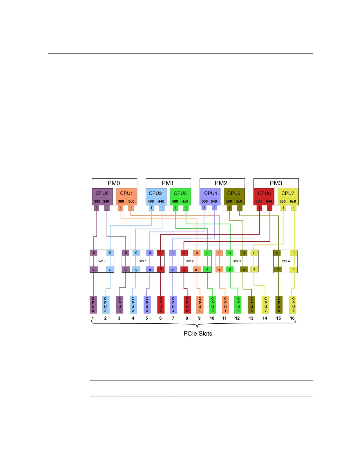
Root Complex Connections (Four Processor
Modules)
This diagram illustrates the root complex connections between the four processor modules and
the 16 PCIe I/O slots in a fully-populated server. Each CPU supports two I/O root complexes.
Each root complex connects to two I/O slots through two of five multiplexing switches.
The port ID values shown in the diagram correspond to the pci@ values reported in the
OpenBoot show-devs command output. For example:
PM CPU Switch I/O Slot Root Complex Path
0 0 0 1
/pci@300/pci@1/pci@0/pci@6
 Loading...