3
9850067 R01 - 2020-2021 GENERAL / GENERAL XP Service Manual
© Copyright Polaris Inc.
3.37
CRANKSHAFT REMOVAL / INSPECTION
1. Perform Crankcase Disassembly / Inspection page
3.33 procedure.
2. Perform Balance Shaft Removal / Inspection page
3.36 procedure.
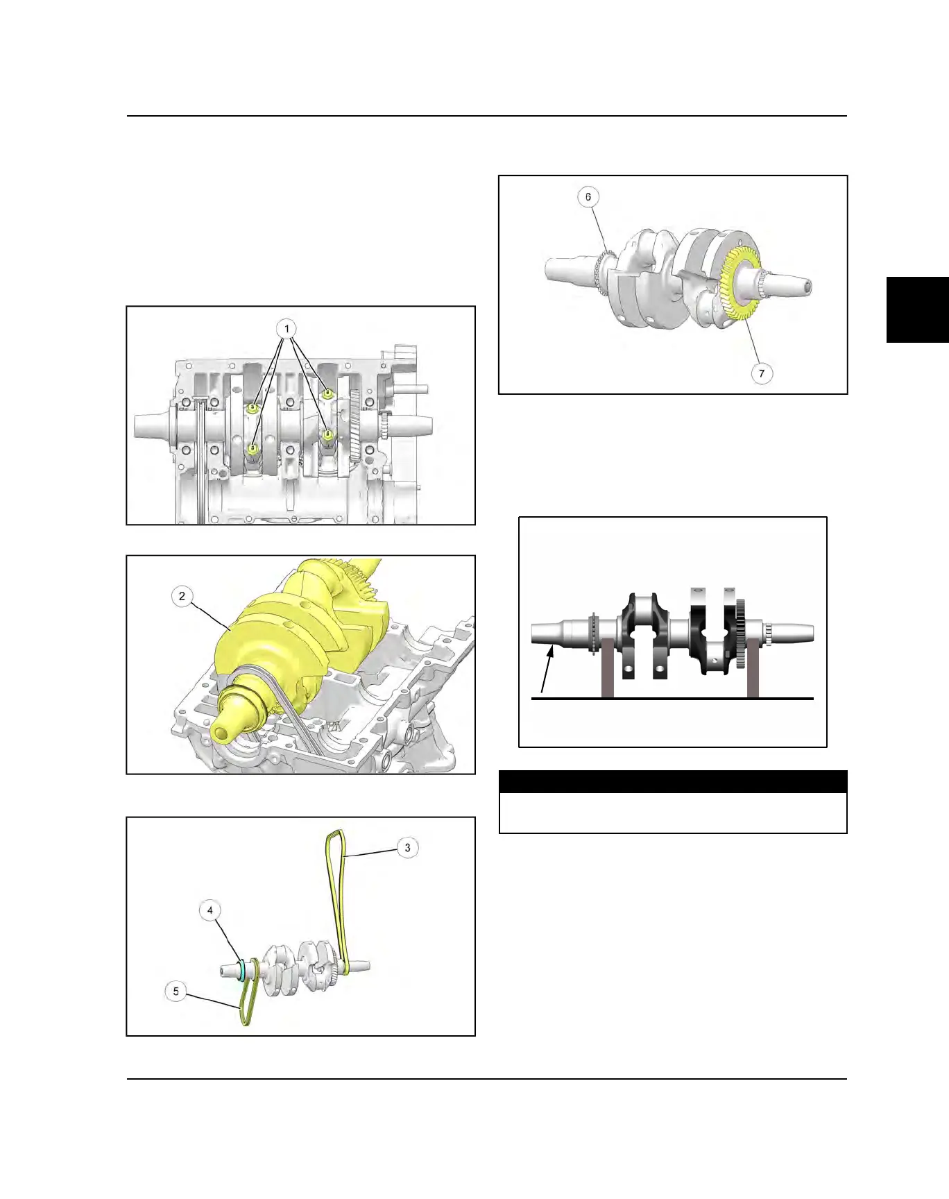
3. For ease of assembly, mark each connecting rod and
end cap.
4. Loosen, remove and discard the four connecting rod
bolts
q
. Remove the end caps from the crankshaft.
5. Carefully lift the crankshaft
w
out of the crankcase.
6. Remove the cam chain
e
, oil pump drive chain
t
and PTO main seal
r
from the crankshaft.
7. Inspect the crankshaft gear
u
and auxiliary sprocket
y
for broken or worn teeth.
8. If the crankshaft gear or sprocket is damaged, the
crankshaft assembly must be replaced.
9. Support crankshaft on V-blocks or on-centers in a
crankshaft stand or lathe. Measure crankshaft run-
out and replace if run-out exceeds maximum listed
below.
MEASUREMENT
Crankshaft Maximum Runout:
Less than .001″ (0.025 mm)
10. Visually inspect surface of crankshaft main and
connecting rod journals. Replace crankshaft if any
journal is scratched or pitted.
ENGINE / COOLING SYSTEM

 Loading...