ESP-LXIVM Controller
ESP-LXIVM Series Controllers
13
Loop Pattern
A Loop Pattern supports the greatest distance from controller to IVM
Devices.
The Loop Pattern requires that the 2-Wire path loop back and return
to the controller. The critical path for a Loop design is determined by
calculating the distance around the loop to the farthest IVM Device
and back to the controller. For both the Star and Loop designs, dif-
ferent distances can be supported with larger gauge cable.
Maximum Critical Path Lengths for 2-Wire Paths
Nominal
Wire Size
Ohms per 1000’
or Ohms per Km
(per conductor)
Star Loop
Km Miles Km Miles
2.5 mm 7.5 Ohms/Km 3.00 1.86 12.00 7.46
14 AWG 2.58 Ohms/1000’ 2.66 1.65 10.63 6.61
12 AWG 1.62 Ohms/1000’ 4.23 2.63 16.93 10.52
10 AWG 1.02 Ohms/1000’ 6.72 4.18 26.89 16.71
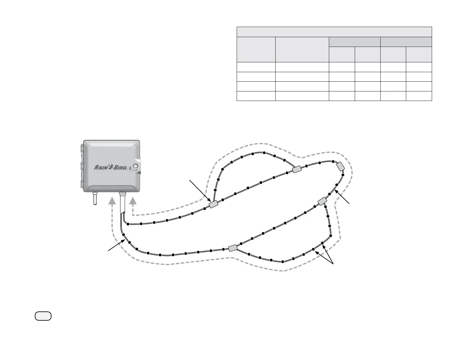
Valve Boxes
2-Wire splice at
branch takeoff s
allow easy breaking
of a loop for
troubleshooting
IVM Devices
Critical Path
Total cable length of
the loop’s critical path
(maximum 6.61 miles
(10.63 km) using
14 AWG cable)
Branch #2 Loop
Main Trunk Loop
2-Wire
Loop
Branch #1 Loop
2-Wire Loop Pattern design showing IVM Devices and Valves
 Loading...