54
ESP-LXIVM Series Controllers
Controller Output
If one or more 2-Wire Devices are not working properly, you can run
Controller Output diagnostic tests at the controller.
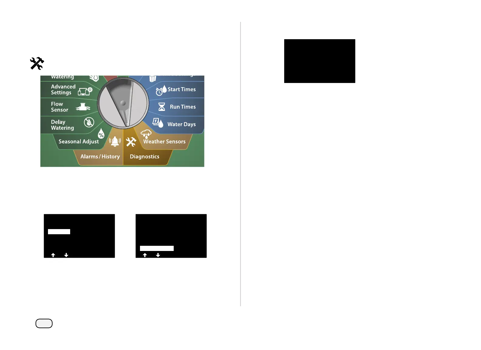
Turn the controller dial to Diagnostics
At the DIAGNOSTICS screen, press the Down Arrow key to select
Diagnostics, then press Next.
At the second DIAGNOSTICS screen, press the Down Arrow key to
select Controller Output, then press Next.
DIAGNOSTICS
Test All Stations
Diagnostics
Confirm Programming
DIAGNOSTICS
List Not Responding
List Responding
Ping Valve/Sensor
Test Shorted Paths
Controller Output
The Controller Output results will be shown on a single screen.
CONTROLLER OUTPUT
Current: 1 mA
Expcted Current
Range 1 mA to 400 mA
Voltage: 25.9
OK if above 23V
NOTE: Current readings show all four 2-Wire paths combined
and not a particular path.
Interpreting Controller Output Results
Controller Output checks line voltage and milliamp draw.
Use the range (1 mA to 400mA , Above 23V) to determine if the cur-
rent are voltage values are outside the limits. If the Controller Output
current or voltage values are outside the limits, follow these steps:
1. Remove all 2-Wire path wires from the IVM 2-Wire Interface
Module and rerun the Controller Output test. Readings should
now be within limits.
2. Reconnect one 2-Wire path wire to the IVM 2-Wire Interface
Module at a time. Then rerun the Controller Output test. If the
survey results are outside the limits then the 2-Wire path wire
that is connected is the source of the problem.
3. Check the 2-Wire path, splices and 2-Wire Device splices for
shorted wires or leaks to ground.
4. Press the 2-Wire Diagnostics/Ping 2-Wire Device feature to
determine which 2-Wire Devices the LX-IVM controller can
communicate with and which devices it cannot communicate
with. The 2-Wire splices between the last 2-Wire Device that
responds and the first device that does not respond is likely the
location of the problem.
 Loading...