Remote control commands
R&S
®
NRPxxS(N)
80User Manual 1177.5079.02 ─ 15
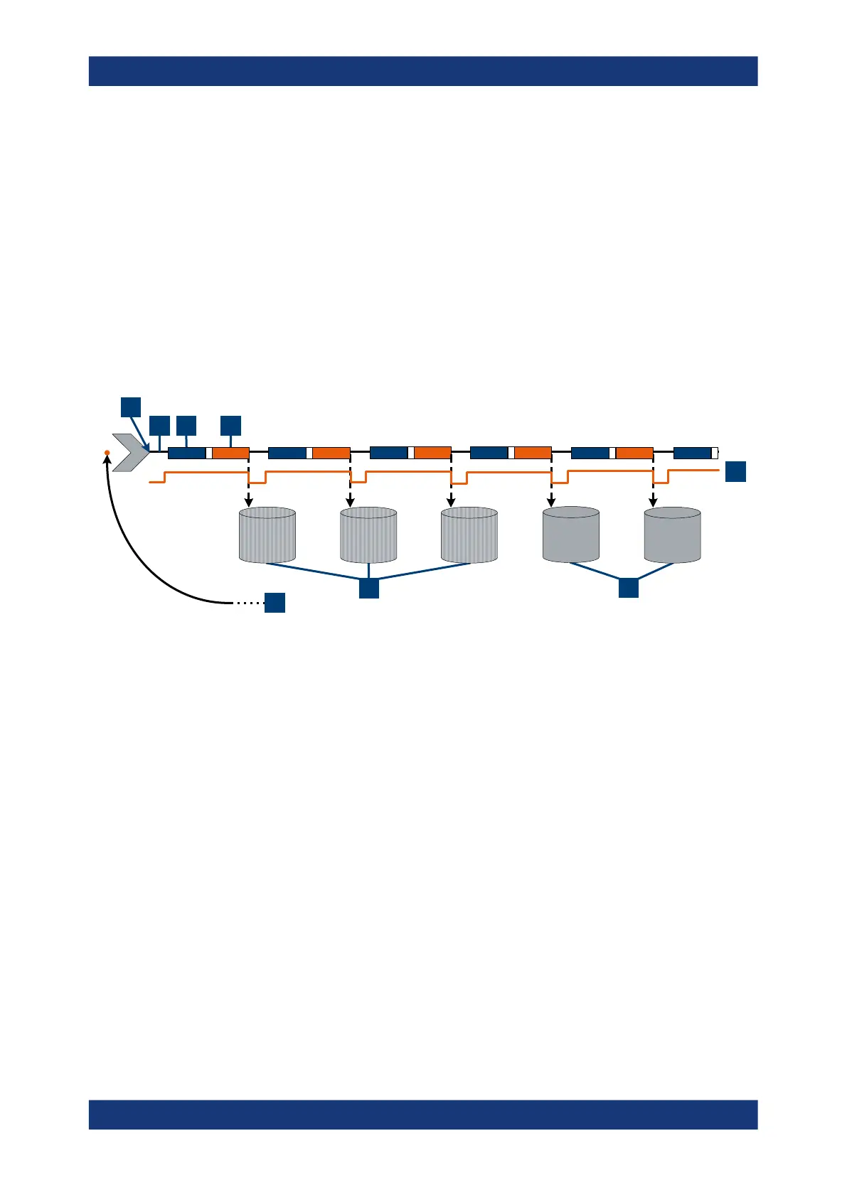
Example: Moving termination control
Further settings for this example:
●
[SENSe<Sensor>:]AVERage:TCONtrol MOVing
●
TRIGger:COUNt 16
Every measurement is started by a trigger event. Due to the chopper phases, one
measurement lasts twice the defined aperture time. During each measurement, the
trigger synchronization is high (TRIGger:SYNC:STATe ON). Every measurement pro-
vides a result. During the settling phase, the amount of the result is already correct, but
the noise is higher. After 4 measurements, when the average count is reached, settled
data is available.
When the trigger count is reached (TRIGger:COUNt on page 84), the power sensor
returns to the idle state.
1
3 4
2
5
6
7
8
1
= Start of the measurement cycle
2 = Trigger events
3 = Noninverted chopper phase
4 = Inverted chopper phase
5 = Trigger synchronization
6 = Averaged measurement result after average count is reached
7 = Measurement result before average count is reached
8 = Return to idle state after trigger count (= 16 in this example) is reached
Controlling the measurement

 Loading...

