— English Vacuum spray degassing — 20.05.2019
. Attach the ball valve (green handle) for the "WC" make-
up connection.
– If the automatic make-up is not connected, close
the "WC" connection with an external thread ½ "
blind plug.
. Attach the ball valve (red handle) with the "ST" dirt trap
at the "DC" inlet of the degassing.
. Attach the ball valve (blue handle) at the "DC" outlet of
the degassing.
Wall mounting
Use the holes provided at the rear of the housing to attach the
device at the wall. Select the attachment means according to
the wall properties and the weight of the device.
6.3.3 Degassing line to the system
Installation detail of the "DC" degassing line
Install the "DC" degassing lines as follows:
Prevent an overload of the "ST" dirt trap in the device
caused by coarse dirt.
Install the gas-rich degassing pipe “DC” upstream of the
gas-poor degassing pipe (when viewed in the system
flow direction).
Preferably install on the return side of the facility
system.
– The water temperature must be in the range of 0
°C – 70 °C to ensure sufficient degassing
capacity.
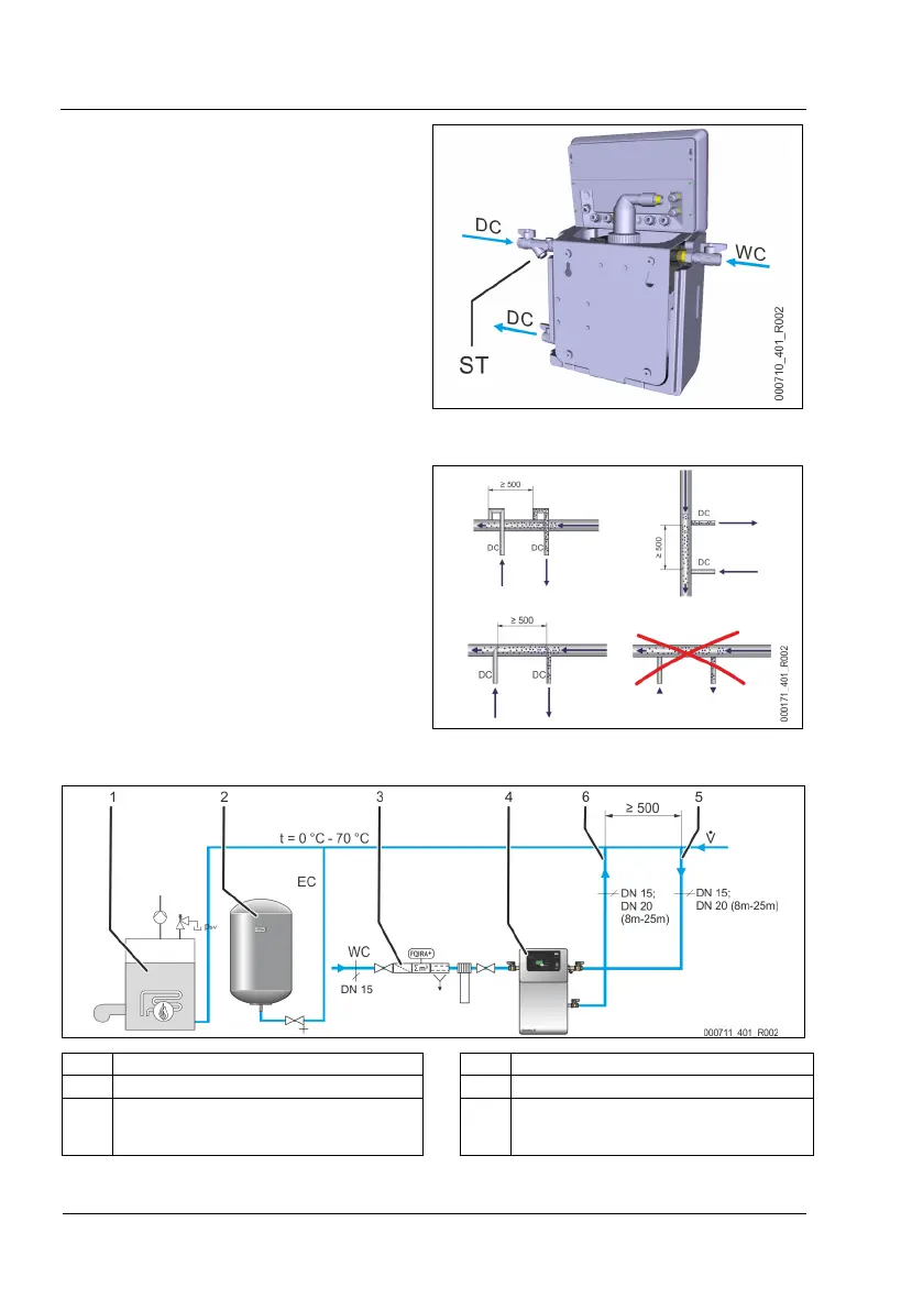
Device installation in a heating system – Pressure maintenance with bladder "MAG" expansion vessel
1 Heating system 4 Device
2 Expansion vessel 5 "DC" degassing line (gas-rich water)
3 For optional equipment and accessories, see
chapter 4.5 "Optional equipment and accessories"
on page 10
6 "DC" degassing line (degassed water)
 Loading...
