— English Vacuum spray degassing — 20.05.2019
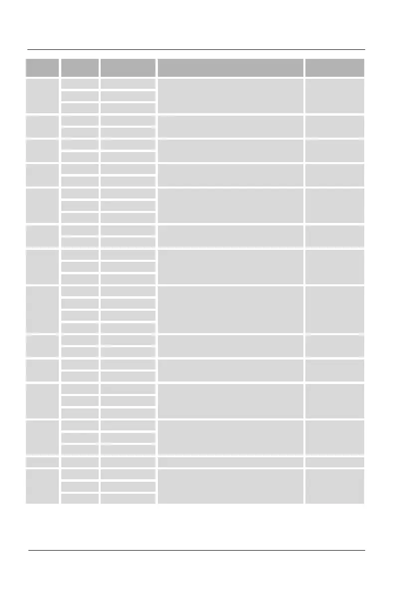
1
1 GND
RS485 interface User, optional 2 A
3 B
2
4 P3
Make-up signal (230 V) User, optional
5 P4
3
6 WM1
Insufficient water external - digital input. User, optional
7 WM2
4
8 K1
Contact water meter User, optional
9 K2
5
10 24 V
Conductivity - analogue input 4-20 mA User, optional 11 INP
12 GND
6
13 WM1
Insufficient water - digital input/ User, optional
14 WM2
7
15 24 V
Pressure sensor - Analogue input 4-20 mA Factory 16 INP
17 GND
8
18 GND
Ball control valve User, optional
19 24 V
20 OUT
21 AIN
9
22 N
Motorized ball valve on the make-up side Factory
23 M3
10
24 N
Motorized ball valve on the system side Factory
25 M2
11
26 C
Error - group message (floating) (230 V) User, optional 27 NC
28 NO
12
29 N
"PU" vacuum pump for degassing. Factory 30 M1
31 PE
13 32 PE Earthing Factory
14
33 PE
230 V power supply via mains cable and plug. Factory 34 N
35 L
 Loading...
