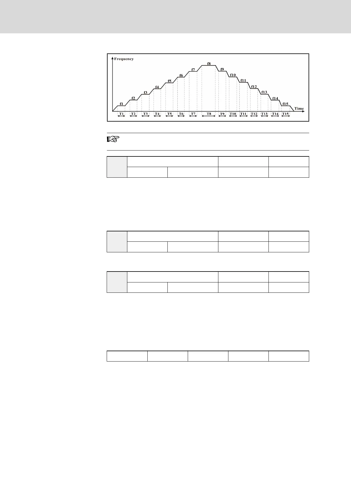
Fig. 7-41: Logic control
f1...f15 are set by parameters E2.06...E2.20, and T1...T15 are set
by parameters E2.22...E2.52.
E2.21
Logic control mode Factory default 0
Setting range 0...3 Minimum unit 1
● 0: Inactive. Logic control is inactive.
● 1: Mode 1. Logic control stops after one cycle.
● 2: Mode 2. Frequency converter runs repeatedly, will be stopped by stop
commands.
● 3: Mode 3. Frequency converter keeps running at the set frequency of
the last phase after one cycle.
E2.22
Logic control time factor Factory default 1
Setting range 1...60 Minimum unit 1
The actual run time of each stage is "Set time × parameter ‘Logic control time
factor’ E2.22".
E2.23
Stage 1 action selection Factory default 0
Setting range 0...31 Minimum unit 1
● The set frequency of stage 1 is defined by parameter ‘Multi-speed fre‐
quency 1’ E2.06.
● Used to define running direction and acceleration / deceleration time of
stage 1.
● To set '0...31', a binary to decimal conversion is needed based on the
data format shown in the table below and the options for each bit below
the table.
bit4 bit3 bit2 bit1 bit0
Tab. 7-16: Binary format of parameter E2.23
● The options of each bit are listed below.
– bit4
– 0: Forward
– 1: Reverse
– bit3 and bit2
– 00: set by parameter ‘Acceleration time 1’ b1.09
– 01: set by parameter ‘Acceleration time 2’ E2.00
– 10: set by parameter ‘Acceleration time 3’ E2.02
Bosch Rexroth AG DOK-RCON02-FV*********-IB08-EN-P146/259
Rexroth Frequency Converter Fv
Parameter Settings