Do you have a question about the Ricoh D096 and is the answer not in the manual?
Important safety measures to prevent injury during machine operation and maintenance.
Precautions regarding toner and developer contact, and necessary first aid.
Emphasizes installation and maintenance by trained customer service representatives.
Guidelines for safe and environmentally sound disposal of toner and parts.
Detailed safety instructions for handling toner to avoid spills, inhalation, or skin contact.
Critical safety information regarding laser unit repair and handling procedures.
Explains common symbols and abbreviations used throughout the manual.
Lists general specifications, paper sizes, and optional equipment for the copier.
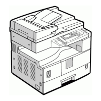
Details the machine's components and their corresponding codes and diagrams.
Compares D096 features to predecessor models like B245 for user transition.
Provides a general understanding of the machine's layout and internal structure.
Illustrates and labels various internal components of the machine for identification.
Diagrams the routes paper takes through the machine from different entry points.
Shows the arrangement of gears and motors that drive the machine's mechanisms.
Outlines environmental, electrical, and physical conditions necessary for proper machine setup.
Specifies acceptable temperature, humidity, illumination, ventilation, and dust levels for operation.
Details the required levelness for the machine to ensure correct operation and prevent issues.
Defines the clearance needed around the machine for airflow and access during operation.
Lists the electrical input voltage, frequency, and amperage specifications for the machine.
Guides the user through the process of installing the copier unit and its accessories.
Identifies specific sockets for connecting optional peripherals like ADF and paper trays.
Instructs users to verify the presence of all necessary installation accessories.
Provides step-by-step instructions for physically installing the main copier unit.
Details the procedure for installing an optional platen cover for the machine.
Lists the accessories required for platen cover installation.
Step-by-step guide for attaching the platen cover to the machine.
Outlines the process for installing the optional Automatic Document Feeder.
Lists all accessories needed for the ADF installation.
Step-by-step instructions for mounting and connecting the ADF unit.
Describes how to install an anti-condensation heater to prevent moisture buildup.
Details the installation process for an optional tray heater.
Step-by-step guide for installing the tray heater component.
Instructions for attaching an accessibility handle to the paper tray.
Refers to appendices for tables detailing scheduled maintenance tasks and intervals.
Step-by-step guide on resetting the preventive maintenance timer after service.
Important safety and handling precautions before performing any component replacement or adjustment.
Precautions for handling the PCU, including drum surface care and disposal.
Cautions for handling the transfer roller to avoid damage to its surface.
Guidelines for cleaning scanner components and handling the lens unit.
Precautions for working with the laser unit, including dust sensitivity and handling.
Cautions related to the hot fusing unit, including handling hot components and lamps.
Notes on handling paper feed rollers and ensuring correct paper size settings.
Lists specific tools and lubricants recommended for maintenance and repair procedures.
Instructions for removing and installing various external covers and the operation panel.
Steps to remove and replace the rear cover of the machine.
Procedure for removing and installing the copy tray.
Steps for removing and replacing the machine's upper exterior covers.
Instructions on how to remove and reinstall the left side cover.
Procedure for removing and reinstalling the front cover of the machine.
Steps for removing and reinstalling the front right cover.
Instructions for removing and reinstalling the right rear cover.
Steps for opening and disconnecting the right door for access.
Procedures for removing and reinstalling the by-pass tray.
Steps for accessing and replacing the platen cover sensor.
Details the replacement and adjustment procedures for the scanner unit components.
Instructions for cleaning and replacing the exposure glass components.
Procedure for removing and installing the scanner lens block.
Steps for replacing the lamp stabilizer board and exposure lamp.
Guide for replacing the scanner motor and its associated parts.
Procedure for replacing the scanner home position sensor.
Instructions for aligning the scanner units for optimal image capture.
Procedures for replacing and adjusting components within the laser unit.
Identifies the location of important laser safety caution decals on the unit.
Steps for removing and reinstalling the toner shield glass.
Procedure for removing and installing the main laser unit.
Steps for replacing the LD unit within the laser assembly.
Guide for replacing the polygonal mirror motor.
Detailed procedure for aligning the laser unit for correct image output.
Procedures for replacing and servicing components related to the Photoconductor Unit (PCU).
Steps for removing and reinstalling the Photoconductor Unit (PCU).
Procedure for replacing the toner supply motor.
Steps for replacing pick-off pawls and the toner density sensor.
Procedure for replacing the OPC drum within the PCU.
Steps for replacing the charge roller and cleaning brush assembly.
Procedure for replacing the cleaning blade in the PCU.
Instructions for handling and loading developer into the PCU.
Post-maintenance checks and copy quality adjustments after PCU work.
Procedures for replacing and servicing paper feed components.
Steps for removing and installing the paper feed roller.
Procedure for replacing the friction pad.
Steps for replacing the paper end sensor.
Procedure for replacing the paper exit sensor.
Steps for replacing the by-pass feed roller and sensor.
Procedure for replacing the registration roller.
Steps for replacing the by-pass paper size switch.
Procedure for replacing the registration clutch.
Steps for replacing the registration sensor.
Procedure for replacing paper feed and by-pass feed clutches.
Steps for replacing the paper size switch.
Procedures for replacing and servicing image transfer components.
Steps for replacing the image transfer roller.
Procedure for replacing the image density sensor.
Procedures for replacing and servicing fusing unit components.
Steps for removing and installing the fusing unit.
Procedure for replacing the thermistor in the fusing unit.
Steps for replacing the fusing lamps.
Procedure for replacing hot roller stripper pawls.
Steps for replacing the hot roller.
Procedure for replacing the thermostat.
Steps for replacing the pressure roller and its bushings.
Procedure for adjusting the nip band width for optimal fusing.
Steps for replacing the cleaning roller.
Covers replacement procedures for various other machine components.
Procedure for replacing the quenching lamp.
Steps for replacing the high-voltage power supply board.
Procedure for replacing the Base-Engine Image Control Unit (BICU).
Steps for replacing the main motor.
Procedure for replacing the left exhaust fan.
Steps for replacing the Power Supply Unit (PSU).
Procedures for replacing gearbox components and their arrangement.
Guides for making image adjustments for printing and scanning.
Procedures for adjusting print registration, magnification, and margins.
Procedures for adjusting scanner registration, magnification, and density.
Instructions for adjusting image quality settings specific to the ADF.
Information on accessing and using the Service Program (SP) mode for maintenance.
Refers to appendices for detailed Service Program tables.
Step-by-step guide on how to access the machine's Service Program mode.
Explains various Service Program modes for machine adjustment and diagnostics.
Outlines a procedure for adjusting image registration and magnification using SP modes.
Details how to analyze ID sensor errors using SP 2221 for troubleshooting.
Instructions for clearing machine settings and counters stored in NVRAM using SP 5801.
Guide on using SP 5803 to check the status of machine sensors and switches.
Instructions for using SP 5804 to test the operation of machine components.
Procedure for inputting the machine's serial number using SP 5811.
Steps for backing up and restoring NVRAM data to/from a flash memory card.
Guide on how to update the machine's firmware using a flash memory card.
Instructions for printing various test patterns using SP 5902 for calibration.
Explains how to view paper jam counts by timing and location using SP 7504.
How to print machine status lists using SP 5990.
Procedure to view the history of original jams using SP 7508.
Lists and explains codes related to original jam history.
How to display ADF original size sensor output using SP 6901.
Refers to appendices for information on service call conditions.
Details common electrical component failures and their symptoms.
Lists sensor issues, their conditions (open/shorted), and resulting symptoms.
Describes problems related to various switches and their operational impact.
Provides a table of fuses and their ratings found on the power supply board.
Describes LED indicators on the BICU and their functions.
Information about the LED indicator on the BICU and its monitoring function.
Discusses energy-saving modes and their proper usage for efficiency.
Explains the concept and operation of energy saver modes and timers.
Details how to measure and estimate the effectiveness of energy-saving features using SP 8941.
Provides detailed specifications for configuration, paper handling, power, and dimensions.
Lists supported paper sizes and their detection capabilities across regions and models.
Details how the DF detects original sizes via sensors and region-specific tables.
Information on paper feed and exit capabilities for the main frame tray across regions.
Specifications for optional equipment, focusing on the Automatic Document Feeder (ADF).
Detailed specifications for the ADF, including size, weight, and capacity.
Provides tables outlining scheduled maintenance tasks for various machine components.
Summarizes different levels of service call conditions and their reset procedures.
A summary table of service call condition levels, definitions, and reset methods.
Lists Service Call (SC) codes, their symptoms, and potential causes for troubleshooting.
Comprehensive tables detailing various Service Program (SP) modes and their functions.
SP codes related to paper feed timing and registration adjustments.
SP codes for adjusting drum-related parameters like bias and erase margins.
SP codes for adjusting scanner magnification, registration, and image quality.
SP codes related to machine modes, counter settings, and special functions.
SP codes for adjusting and managing peripheral devices like the ADF.
SP codes for accessing data logs, counters, and history information.
SP codes for retrieving historical data related to prints, jams, and paper usage.
Illustrates and labels the mechanical parts of the document feeder for identification.
Diagrams and labels the electrical components and sensors within the document feeder.
Shows the arrangement of motors and gears responsible for driving the document feeder's mechanisms.
Describes the line speeds and applicability of ADF B813 and ARDF B814 models.
Explains how the document feeder detects original width and length using sensors.
Details the mechanism for picking up and separating originals for feeding.
Describes the path and movement of originals through the document feeder.
Explains the stamping function, its control, and position adjustment using SP6-010.
Presents timing diagrams for various document feeder operations and signals.
Timing chart specifically for A3 paper size and stamp mode operations.
Defines different jam detection conditions (JAM 1-7) and their causes.
Illustrates the electrical connections and control flow between the DF and mainframe.
Instructions on how to perform a free run test using DIP switch settings.
Procedures for removing and replacing the document feeder's exterior covers.
Steps for removing and reinstalling the rear cover of the DF.
Procedure for removing and reinstalling the original table.
Steps for removing and reinstalling the front cover.
Instructions for removing and reinstalling the original entrance guide.
Procedure for removing and reinstalling the DF feed cover.
Steps for removing and reinstalling the feed unit assembly.
Procedure for replacing the separation roller.
Steps for replacing the pick-up roller.
Procedure for removing and installing the feed belt.
Steps for replacing width, length, and trailing edge sensors.
Procedure for replacing the original set sensor.
Steps for replacing the transport motor.
Procedures for replacing feed cover sensor, feed clutch, ROM, and DF drive board.
Steps for replacing the registration sensor.
Procedure for replacing the pick-up solenoid.
Steps for removing and replacing the stamp solenoid.
| Brand | Ricoh |
|---|---|
| Model | D096 |
| Category | All in One Printer |
| Language | English |