4. BASIC OPERATION
IMR02L04-E3
4-24
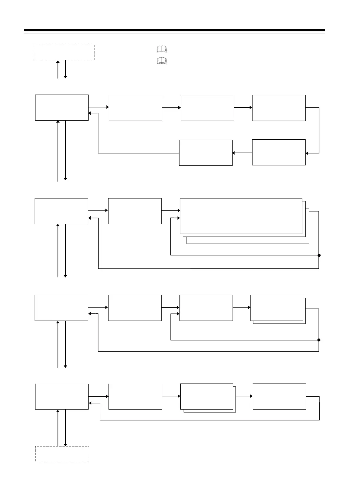
Level PID
setting block
PV
LV.PID
M:S
SV
30000000200
PV
LEVL.1
$
M:S
SV
PID00000000
Level PID setting 1
PV
LEVL.7
$
M:S
SV
PID00000000
Level PID setting 7
Level PID setting 2
to
Level PID setting 6
16.E.TM: Time signal end time
Time signal memory
group setting block
PV
TM.SIG
M:S
SV
30000000200
PV
P TS.GR
M:S
SV
53000000001
Time signal memory
group number
Output program memory
group setting block
*
PV
PRG.MV
M:S
SV
30000000200
PV
P.M V.GR
M:S
SV
53000000001
Output program memory
group number
PV
0 P.M V 1
%
M:S
SV
GR.0 1 00-005.0
Output program value 1
Output program
value 2,
Output program
value 3
Go to the setting display of Output program 1, 2 and
3 of the next segment.
Reset mode
setting block
01.OUT: Time signal output assignment
01.S.SN: Start segment of time signal
01.S.TM: Time signal start time
01.E.SN: End segment of time signal
01.E.TM: Time signal end time
After setting parameters of all segments
Go to the setting display of the next memory number.
Setting parameter for each memory number (1 to 16)
(Time signal memory group consists of 16 memories
for setting Time signal.)
PV
WAIT
M:S
SV
FIX000VSCI.1
Wait memory group
setting block
PV
L WT.GR
M:S
SV
F60.01R00001
PV
TM.OUT
M:S
SV
GR.0 1 00000:00
Wait time-out
set value
PV
ZONE.H
$
M:S
SV
GR.0 1 0000000
Wait zone high
PV
ZONE.L
$
M:S
SV
GR.0 1 0000000
PV
RE.TRG
M:S
SV
GR.0 1 0000000
Wait release trigger
selection
Wait memory group
number
Wait zone low
Event memory group
setting block
After setting memory number 16
* Displays when Output program value is assigned to OUT1 to OUT3.
Press the STEP R.SET key to go
ack to the previous display.
Press the STEP R.SET key while pressing the
key to go
back to the first setting display of the setting block.
(P. 4-19)
(P. 4-20)
(P. 4-20)
(P. 4-20)

 Loading...


