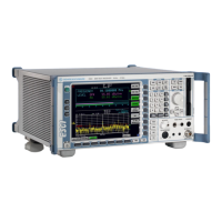
Example - Level and Frequency Measurement R&S ESCI
1166.6004.12 2.2 E-2
Example of Level and Frequency Measurement
Measurement
Measurement and display of RFI signal levels versus frequency is one of the most frequent tasks
performed by an EMI test receiver. In the case of unknown signals, PRESET values will mostly be used
for the measurement. If levels higher than +137 dBµV (10 dB RF attenuation) are expected or possible,
a power attenuator has to be connected in front of the test receiver input. Very high levels may
otherwise damage or destroy the attenuator or input mixer.
Main Test Receiver Functions
The main functions required for the level and frequency measurement are setting the SCAN table
(START FREQUENCY, STOP FREQUENCY, STEPSIZE), selecting the resolution (IF) bandwidth (RES
BW), setting the measurement time (MEAS TIME) and selecting the detectors (eg peak or average) and
MARKER functions required for the analysis.
Measurement Sequence - Level and Frequency Measurement
In this example the spectrum of the signal present at RF INPUT is recorded in the frequency range 150
kHz to 30 MHz. The scan table and associated parameters are manually set.
The example is generally suitable for all fast pre-compliance measurements required for measuring
unknown noise spectra of DUTs in the development stage and for modifying prototypes and can be
used as a basis for final tests later on.
The high speed of fully synthesized scans, the frequency and amplitude accuracy and the wide dynamic
range of Test Receiver R&S ESCI are of utmost importance and very useful for these measurements.
The following measurement steps are performed:
1. PRESET of instrument.
2. Selecting RECEIVER mode (RECEIVER hotkey).
3. Programming the scan table: stop frequency 30 MHz, 1 scan range
4. Selecting detectors, measurement bandwidth and measurement time
5. Applying the signal (RF input)
6. Starting the scan
7. Level analysis in the frequency domain using MARKER function
8. Setting the SPLIT SCREEN function
9. Tuning to the receiver frequency using the TUNE TO MARKER function
10. From overview to standard-conformal measurement
11. Storing test results, tables and diagrams

 Loading...