Confidential Table of Contents
iv English 8/2019. Rev 0.0
Figures
Figure 2-1: Battery Module Type A ......................................................................................................................................... 5
Figure 2-2: Battery Module Type B ......................................................................................................................................... 6
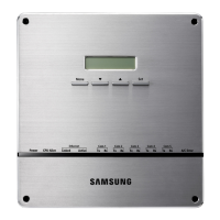
Figure 2-3: SMU ........................................................................................................................................................................ 7
Figure 2-4: Auxiliary Breaker Switch ....................................................................................................................................... 8
Figure 2-5: Terminal Block Isometric View ............................................................................................................................. 8
Figure 2-6: Terminal Block Front / Top View (Cover Opened/Closed) ................................................................................. 9
Figure 2-7: SMPS Assembly Type A ....................................................................................................................................... 10
Figure 2-8: SMPS Assembly Type B ....................................................................................................................................... 11
Figure 2-9: Front View of SMPS Assembly Type A, 3-Phase Input ...................................................................................... 11
Figure 2-10: Front View of SMPS Assembly Type A, 1-Phase Input .................................................................................... 11
Figure 2-11: SMPS Assembly Type A – System BMS Connections ...................................................................................... 11
Figure 2-12: Front View of SMPS Assembly Type B, 1-Phase Input .................................................................................... 12
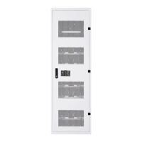
Figure 2-13: Rack Frame ........................................................................................................................................................ 17
Figure 3-1: Installation Procedure ......................................................................................................................................... 20
Figure 3-2: Clearance Distance for Single Rack Frame......................................................................................................... 30
Figure 3-3: Clearance Distance for Multiple Rack Frames Installed Side-by-Side.............................................................. 30
Figure 3-4: Clearance Distance for Multiple Rack Frames Installed Side-by-Side and Rear-to-Rear................................ 31
Figure 3-5: Front panel screws (eight) .................................................................................................................................. 31
Figure 3-6: Front panel hooks (four) ..................................................................................................................................... 32
Figure 3-7: Side panel screws (six) ........................................................................................................................................ 32
Figure 3-8: Side panel hooks (four) ....................................................................................................................................... 33
Figure 3-9: Rear panel screws (eight).................................................................................................................................... 33
Figure 3-10: Rear panel hooks (four) .................................................................................................................................... 34
Figure 3-11: Rack Anchoring Points (4 EA) ........................................................................................................................... 34
Figure 3-12: Holes on the sides of the rack (six) .................................................................................................................. 35
Figure 3-13: Reattaching the Side Panels (four hooks and six screws for each panel) ..................................................... 36
Figure 3-14: Reattaching the Rear Panels ............................................................................................................................. 37
Figure 3-15: Front door ajar................................................................................................................................................... 39
Figure 3-16: Removing the earth cable ................................................................................................................................. 39
Figure 3-17: Removing the front door .................................................................................................................................. 40
Figure 3-18: All doors and front panels removed. ............................................................................................................... 40
Figure 3-19: Inserting SMU .................................................................................................................................................... 41
Figure 3-20: Attaching a SMU to a Rack Frame .................................................................................................................... 41
Figure 3-21: Ground Cable Connection to the SMU ............................................................................................................ 42
Figure 3-22: Inserting SMPS Assembly .................................................................................................................................. 43
Figure 3-23: Attaching the SMPS Assembly .......................................................................................................................... 43
Figure 3-24: Ground Cable Connection to the SMPS Assembly .......................................................................................... 44
Figure 3-25: Insertion of Modules on the Ninth Shelf from the Bottom ............................................................................ 45
Figure 3-26: Battery Module Arrangement on the Eighth Shelf ......................................................................................... 46
Figure 3-27: Battery Module Arrangement .......................................................................................................................... 46
Figure 3-28 : Module Number ............................................................................................................................................... 47
Figure 3-29: Insertion of modules on 1st shelf..................................................................................................................... 47
Figure 3-30: Rack Fuse Busbar Assembly .............................................................................................................................. 48
Figure 3-31: Rack Fuse Busbar Assembly (Fuse Cover) ........................................................................................................ 48
Figure 3-32: Fuse Busbar Left Assembly ............................................................................................................................... 49
Figure 3-33: Fuse Busbar Left Assembly (Fuse Cover) ......................................................................................................... 49
Figure 3-34: Fuse Busbar Right Assembly ............................................................................................................................. 50
Figure 3-35: Fuse Busbar Right Assembly (Fuse Cover) ....................................................................................................... 50
Figure 3-36: Removing the Module #1’s Cover and SMU B- Terminal Cover .................................................................... 52
Figure 3-37: Connect SMU B- and Module #1 B- ................................................................................................................. 52