Home
Samsung
Controller
136S
Page 71 (Figure 3-38: Restore Smus B- Terminal)
Samsung 136S - Figure 3-38: Restore Smus B- Terminal
156 pages
Manual
Save Page as PDF
To Next Page
To Next Page
To Previous Page
To Previous Page
Loading...
Confiden
tia
l
3
.
In
stalling t
he P
r
oduct
English 8
/2019. R
e
v 0.0
53
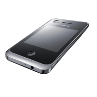
3.
Re
at
t
ach
SMU
’
s B
- term
inal c
over
.
Figure
3-
38
:
Restore SM
U
’s
B
- Term
inal
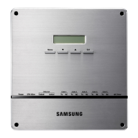
4.
Remo
ve Bat
tery
Mod
ule #2’
s
fr
ont cov
er
.
Figure
3-
39
: Rem
ove Batt
ery
Mo
dule #2’s Fr
ont Co
ver
70
72
Table of Contents
Main Page
Important Safety Instructions
5
General Instructions
6
Safety Precautions
6
Personnel and Equipment Warnings
7
Dangerous Voltages
7
Lock Out/Tag out Guidelines
8
General Warnings
8
Table of Contents
11
Tables
13
Figures
14
1 About this Manual
19
Purpose
19
Target Audience
19
Organization
19
Revision History
20
Acronyms and Abbreviations
21
2 Product Description
22
Major Components
22
Battery Module (Type a / Type B)
23
Figure 2-1: Battery Module Type a
23
Figure 2-2: Battery Module Type B
24
SMU (String Management Unit)
25
Table 2-1: Extra Auxiliary Breaker Switch Connector Description
26
Figure 2-4: Auxiliary Breaker Switch
26
Figure 2-5: Terminal Block Isometric View
26
Table 2-2: Terminal Block Description
27
Figure 2-6: Terminal Block Front / Top View (Cover Opened/Closed)
27
SMPS Assembly (Type a / Type B)
28
Figure 2-7: SMPS Assembly Type a
28
Figure 2-8: SMPS Assembly Type B
29
Figure 2-9: Front View of SMPS Assembly Type A, 3-Phase Input
29
Figure 2-10: Front View of SMPS Assembly Type A, 1-Phase Input
29
Figure 2-11: SMPS Assembly Type a - System BMS Connections
29
Figure 2-12: Front View of SMPS Assembly Type B, 1-Phase Input
30
Table 2-3: RS485 Connector Description
31
Table 2-4: TCP/IP Connector Description
31
Table 2-5: Dry Contact Connector Description
32
Table 2-6: AC Terminal Description (3 Phase)
32
Table 2-7: AC Terminal Description (1 Phase)
32
Table 2-8: Dry Contact Operation (Customer ID = 0)
33
Table 2-9: Dry Contact Operation (Customer ID = 1)
33
Table 2-10: Dry Contact Operation (Customer ID = 2)
33
Rack Frame
35
Figure 2-13: Rack Frame
35
3 Installing the Product
36
Grounding the Battery System
36
Arc Flash Calculations
37
Installation Procedure
38
Figure 3-1: Installation Procedure
38
Table 3-1: Estimated Time for Installation (Based on 136S 3P Installation)
39
Preparation Stage-Procedure
40
Preparation Stage-Unpacking
41
Table 3-2: Parts for 136S 3P Rack
41
Figure 2-3: SMU
41
Preparation Stage-Ground Wire and Tools
42
Ground Wires
42
Ground Wire Fasteners
42
Rack Fasteners (Anchors)
42
Multiple Rack Fasteners
42
Table 3-3: Ground Wire Specifications
42
Table 3-4: Ground Wire Fastener Specification
42
Table 3-5: Rack Fastener Specifications
42
Table 3-6: Rack Fastener Specifications (Side by Side)
42
Preparation Stage-Recommended Tools/Instruments
43
Table 3-7: Recommended Tools and Instruments
43
Preparation Stage-Visual Inspection
45
Inspection of the Rack Frame
45
Inspection of the Modules
45
Inspecting the SMU
45
Table 3-8: Module Voltage and Internal Impedance
45
Inspecting the SMPS Assembly
46
Rack Anchoring Stage
47
Table 3-9: Rack Clearance Distances
47
Figure 3-2: Clearance Distance for Single Rack Frame
48
Figure 3-3: Clearance Distance for Multiple Rack Frames Installed Side-By-Side
48
Figure 3-4: Clearance Distance for Multiple Rack Frames Installed Side-By-Side and Rear-To-Rear
49
Figure 3-5: Front Panel Screws (Eight)
49
Figure 3-6: Front Panel Hooks (Four)
50
Figure 3-7: Side Panel Screws (Six)
50
Figure 3-8: Side Panel Hooks (Four)
51
Figure 3-9: Rear Panel Screws (Eight)
51
Figure 3-10: Rear Panel Hooks (Four)
52
Figure 3-11: Rack Anchoring Points (4 EA)
52
Figure 3-12: Holes on the Sides of the Rack (Six)
53
Figure 3-13: Reattaching the Side Panels (Four Hooks and Six Screws for each Panel)
54
Figure 3-14: Reattaching the Rear Panels
55
Rack Installation Stage
56
Front Door Removal
57
Figure 3-15: Front Door Ajar
57
Figure 3-16: Removing the Earth Cable
57
Figure 3-17: Removing the Front Door
58
Figure 3-18: All Doors and Front Panels Removed
58
SMU and SMPS Assembly Installation
59
Figure 3-19: Inserting SMU
59
Figure 3-20: Attaching a SMU to a Rack Frame
59
Figure 3-21: Ground Cable Connection to the SMU
60
Figure 3-22: Inserting SMPS Assembly
61
Figure 3-23: Attaching the SMPS Assembly
61
Figure 3-24: Ground Cable Connection to the SMPS Assembly
62
Battery Module Installation
63
Figure 3-25: Insertion of Modules on the Ninth Shelf from the Bottom
63
Figure 3-26: Battery Module Arrangement on the Eighth Shelf
64
Figure 3-27: Battery Module Arrangement
64
Figure 3-28 : Module Number
65
Figure 3-29: Insertion of Modules on 1St Shelf
65
Fuse-Busbar Assembly
66
Figure 3-30: Rack Fuse Busbar Assembly
66
Figure 3-31: Rack Fuse Busbar Assembly (Fuse Cover)
66
Figure 3-32: Fuse Busbar Left Assembly
67
Figure 3-33: Fuse Busbar Left Assembly (Fuse Cover)
67
Figure 3-34: Fuse Busbar Right Assembly
68
Figure 3-35: Fuse Busbar Right Assembly (Fuse Cover)
68
Busbar Installation
69
Figure 3-36: Removing the Module #1'S Cover and SMU B- Terminal Cover
70
Figure 3-37: Connect SMU B- and Module #1 B
70
Figure 3-38: Restore Smu's B- Terminal
71
Figure 3-40: Connect Battery Module #1 B+ and Battery Module #2 B
72
Figure 3-42: Remove Battery Module #2'S Front Cover
73
Figure 3-44: Reattach Battery Module #2'S Front Cover
74
Figure 3-46: Connect Battery Module #3 B+ and Module #4 B
75
Figure 3-47: Reattach Battery Module #3'S Front Cover
76
Figure 3-49: Connect Battery Module #4 B+ and Battery Module #5 B
77
Figure 3-50: Reattach Battery Module #4'S Front Cover
78
Figure 3-52: Connect Battery Module #5 B+ and Battery Module #6 B
79
Figure 3-53: Reattach Battery Module #5'S Front Cover
80
Figure 3-55: Connect Battery Module #6 B+ and Battery Module #7 B
81
Figure 3-56: Reattach Battery Module #6'S Front Cover
82
Figure 3-58: Connect Battery Module #7 B+ and Battery Module #8 B
83
Figure 3-60: Remove Battery Modules #9'S Front Cover
84
Figure 3-61: Connect Battery Module #8 B+ and Battery Module #9 B
85
Figure 3-63: Remove Battery Modules #10'S Front Cover
86
Figure 3-65: Reattach Battery Module #9'S Front Cover
87
Figure 3-67: Connect Battery Module #10 B+ and Battery Module #11 B
88
Figure 3-68: Reattach Battery Module #10'S Front Cover
89
Figure 3-70: Connect Battery Module #11 B+ and Battery Module #12 B
90
Figure 3-71: Reattach Module #11'S Front Cover
91
Figure 3-73: Connect Battery Module #12B+ and Battery Module #13 B
92
Figure 3-74: Reattach Module #12'S Front Cover
93
Figure 3-76: Connect Battery Module #13 B+ and Battery Module #14 B
94
Figure 3-77: Reattach Battery Module #13'S Front Cover
95
Figure 3-79: Connect Battery Module #14 B+ and Battery Module #15 B
96
Figure 3-80: Reattach Battery Module #14'S Front Cover
97
Figure 3-82: Connect Battery Module #15 B+ and Battery Module #16 B
98
Figure 3-83: Reattach Battery Module #15'S Front Cover
99
Figure 3-85: Connect Battery Module #16 B+ and Battery Module #17 B
100
Figure 3-86: Reattach Battery Module #15'S Front Cover
101
Figure 3-88: Connect SMU B+ and Module #17 B
102
Module and SMU Signal Cable Connection
103
Figure 3-91: Module #1 to Module #2 Signal Cabling
104
Figure 3-93: Module #3 to Module #4 Signal Cabling
105
Figure 3-95: Module #5 to Module #6 Signal Cabling
106
Figure 3-97: Module #7 to Module #8 Signal Cabling
107
Figure 3-99: Module #9 to Module #10 Signal Cabling
108
Figure 3-101: Module #11 to Module #12 Signal Cabling
109
Figure 3-103: Module #13 to Module #14 Signal Cabling
110
Figure 3-105: Module #15 to Module #16 Signal Cabling
111
Figure 3-107: Pre-Punched Hole for Signal Cable
112
Figure 3-108: Signal Cabling Examples of Left Alignment of SMU
113
Figure 3-109: Termination Resistor Setting for Last SMU
114
SMPS Assembly and SMU Power Cable Connection
115
SMPS Assembly and SMU Signal Cable Connection
116
Figure 3-114: Dry Contact Cable Connection to SMPS Assembly
117
SMPS Assembly AC Input Connection
118
Figure 3-118: AC Input Terminals of SMPS Assembly 1 Phase Type a
119
Figure 3-120: SMPS Assembly 3 Phase Type a - AC Input Terminals with Cables Attached
120
Figure 3-122: SMPS Assembly 1 Phase Type a - AC Input Terminals with Cables Attached
121
Figure 3-125: AC Input Terminals of SMPS Assembly 3 Phase Type B
122
Figure 3-127: AC Input Terminals of SMPS Assembly 1 Phase Type B
123
DC Link Cable Connection
124
Figure 3-129: Connecting the DC Link High Current Terminals
125
AC Input Commissioning
127
BMS Configuration
128
Table 3-10: Required Items for BMS Configuration
128
Table 3-11: Rack BMS Configuration Cable Pin Map
129
Table 3-12: System BMS Configuration Cable Pin Map
130
Table 3-13: System BMS Communication Cable Pin Map
131
Figure 3-133: BATTMON Splash Window
133
Figure 3-135: BATTMON Splash Window
134
Figure 3-138: BATTMON Splash Window : Warning Pop-Up Window
135
Figure 3-141: Cable Connections for Rack BMS Configuration
136
Figure 3-143: Rack BMS Termination Switch and CAN Cable Connection
137
Figure 3-145: BATTMON Splash Window
138
Figure 3-147: Rack BMS Config Setting Window
139
Figure 3-148: Cable Connections for System BMS Configuration
140
Figure 3-150: BATTMON Splash Window
141
Figure 3-152: System BMS Install Setting Window
142
Communication Check
143
Figure 3-154: Open "Network and Sharing Center
144
Figure 3-156: Open "Properties" for "Local Area Connection
145
Figure 3-158: Setting the Computer's IP Address
146
Figure 3-159: BATTMON Icon
147
Figure 3-162: System and Rack Information
148
Figure 3-164: Cell Information
149
Reinstall the Front Door
150
Reinstall the Front Panel
151
Switching on the MCCB
152
Related product manuals
Samsung SSC-1000
13 pages
Samsung SCC-1000
13 pages
Samsung SPC-1010
13 pages
Samsung Function controller
16 pages
Samsung MCM-A100
16 pages
Samsung SCC-3100A
50 pages
Samsung SPC-7000
30 pages
Samsung MIM-H02
36 pages
Samsung RMC30D1
30 pages
Samsung DMS2.5
32 pages
Samsung SPC-2000
9 pages
MCM-A200 User Manual (XP)
8 pages