Confidential 3. Installing the Product
English 8/2019. Rev 0.0 23
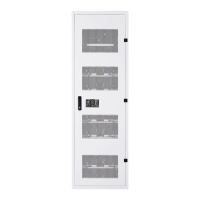
3.5 Preparation Stage—Unpacking
Check the following parts during unpacking:
Table 3-2: Parts for 136S 3P Rack
V808-00066A: White, for specific customer
V808-00068A: Black, for general customer
X = 1 for specific customer
X = 3 for general customer
Y = 2 for specific customer
Y = 4 for general customer
X = A for general customer
X = B for specific customer
SMPS ASSEMBLY Type A
(WITH SYSTEM BMS ASSEMBLY)
V044-0004AA (1 Phase)
V044-0006AA (3 phase)
For Rack #1
X = A for general customer
X = B for specific customer
V044-0005AA (1 phase)
SJ94-00238B (3 phase)
For Rack #2, 3
For general customer
High current bus bar connection for modules
Connect between modules #8 and #9
Connect between modules #8 and #9
Connect between modules #5 and #6, between modules #8 and #9,
and between modules #14 and #15
Fuse cover for fuse between modules #8 and #9
Fuse cover for fuse between modules #5 and #6, and between
modules #14 and #15
Connect between modules #14 and #15
Connect between modules #14 and #15
Connect between modules #5 and #6
Connect between modules #5 and #6
Connect Battery Module #1 and SMU.
WIRE ASSY MODULE TO MODULE #1
Signal Connection for Modules
WIRE ASSY RACK TO RACK #2
Connect Rack between #1, #2 and #3.
Connect the Rack BMS CAN connector in the SMU to the System BMS
CAN connector in the SMPS ASSEMBLY.
Connect the Rack BMS DC IN to SMPS ASSEMBLY DC OUT
WIRE ASSY MODULE TO MODULE #2
Signal connection between modules #8 and #9
Connecting SMPS Assembly and SMU to Rack Frame.
Mounting SMU, SMPS, and WIRE ASSY EARTH to Rack Frame
Mounting Busbar to Module
Mounting Busbar to Switchgrear
Mounting Fuse Busbar to Fuse
Mounting Rack Frame to Rack Frame side by side
Mounting Rack Frame to Rack Frame side by side
Mounting Rack Frame to Rack Frame side by side
Connect to MCCB Aux Contact
Connect to SMPS Assembly DRY CONTACT