Saia-Burgess Controls AG
Manual Manual PCD 1 / PCD 2 Series │ Document 26 / 737 EN22 │ 2013-11-26
Appendix
A-6
Installation direction and relays contact protection
A
A.4 Installationdirectionandrelayscontactprotection
A.4.1 Installationdirectionforswitchinglowvoltages
For reasons of safety it is not allowed that low voltages (up to 50 V) and higher volt-
ages (50 … 250 V) are connected to the same module.
If a Saia PCD
®
system module is connected to a higher voltage (50 … 250 V) ap-
proved components for this voltage have to be used for all elements which are gal-
vanically connected to the system.
Using higher voltage (50 … 250 V), all connections to the relay contacts are to be con-
nected on the same circuit. That means at one point in such a way that they are all
protected against one AC-phase by only one fuse. Each load circuit may be protected
individually by a fuse of max. 2 A.
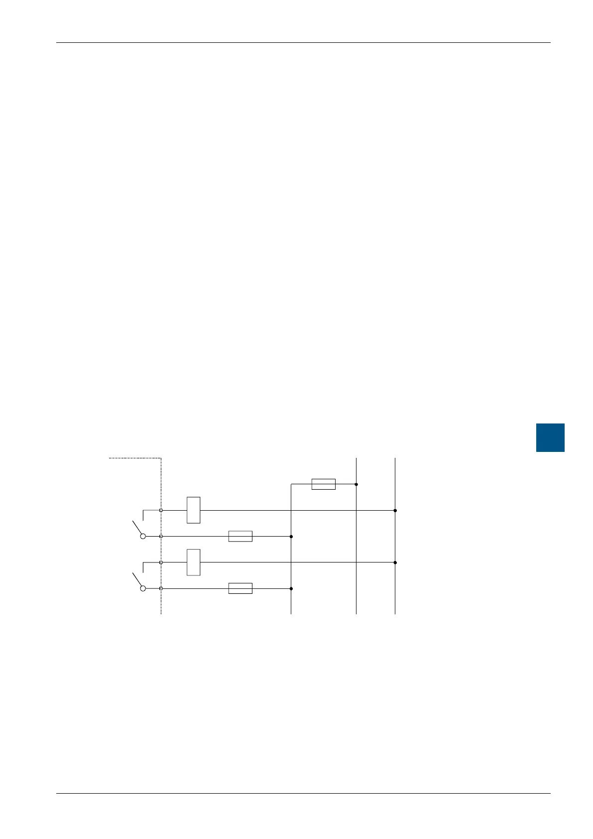
A.4.2 Installationdirectionforswitchinghighervoltages
For reasons of safety it is not allowed that low voltages (up to 50 V) and higher volt-
ages (50 … 250 V) are connected to the same module.
If a Saia PCD
®
system module is connected to a higher voltage (50 … 250 V) ap-
proved components for this voltage have to be used for all elements which are gal-
vanically connected to the system.
Using higher voltage (50 … 250 V), all connections to the relay contacts are to be con-
nected on the same circuit. That means at one point in such a way that they are all
protected against one AC-phase by only one fuse. Each load circuit may be protected
individually by a fuse of max. 2A.
PCD2.A200
L N
Burden
max. 10 A
max. 2 A