Saia-Burgess Controls AG
Manual Manual PCD 1 / PCD 2 Series │ Document 26 / 737 EN22 │ 2013-11-26
4
Communication interfaces
4-19
Serial interfaces on socket A
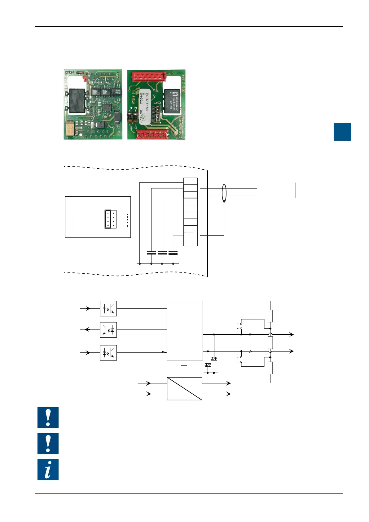
4.6.5 RS-485 with PCD7.F150, Port #1 (without PCD1.M110)
PCD7.F150:
RS-485 electrically isolated, with line
termination resistors capable of activation, for
socket A
The electrical isolation is achieved with 3
optocouplers and a DC / DC transducer.
The data signals are protected against
surges by a suppressor diode (10 V). The
line termination resistors can be connect-
ed / disconnected with a jumper.
Connections
10
12
14
16
17
19
J1
CLOSED
PGND
SGND
Port1 (X4)
RX - TX
/RX - /TX
D
/D
RS-485 Bus
50 VDC
S-Bus
SGND (electrically isolated,
must be connected to the
cables shield).
Supply (Terminal 22/23)
Socket A
Block diagram:
TXD
RXD
RTS
75176
OPTO-0601
SGND
+5VE
330 Ohm
150 Ohm
330 Ohm
D
/D
+5V
PGND
SGND
+5VE
EN
SGND
Transmit
Receive
RS-485
Driver
DC
DC
Not all manufacturers use the same connection conguration, so the data lines may
need to be crossed.
The potential difference between PGND and the data lines Rx-Tx, Rx- / Tx
(and SGND) is limited to 50 V by a suppressor capacitor.
For installation details, see manual 26 / 740 :
“Installation components for RS-485 networks”.