Saia-Burgess Controls AG
Manual Manual PCD 1 / PCD 2 Series │ Document 26 / 737 EN22 │ 2013-11-26
5
Input/output (I/O) modules
5-81
Analogue output modules
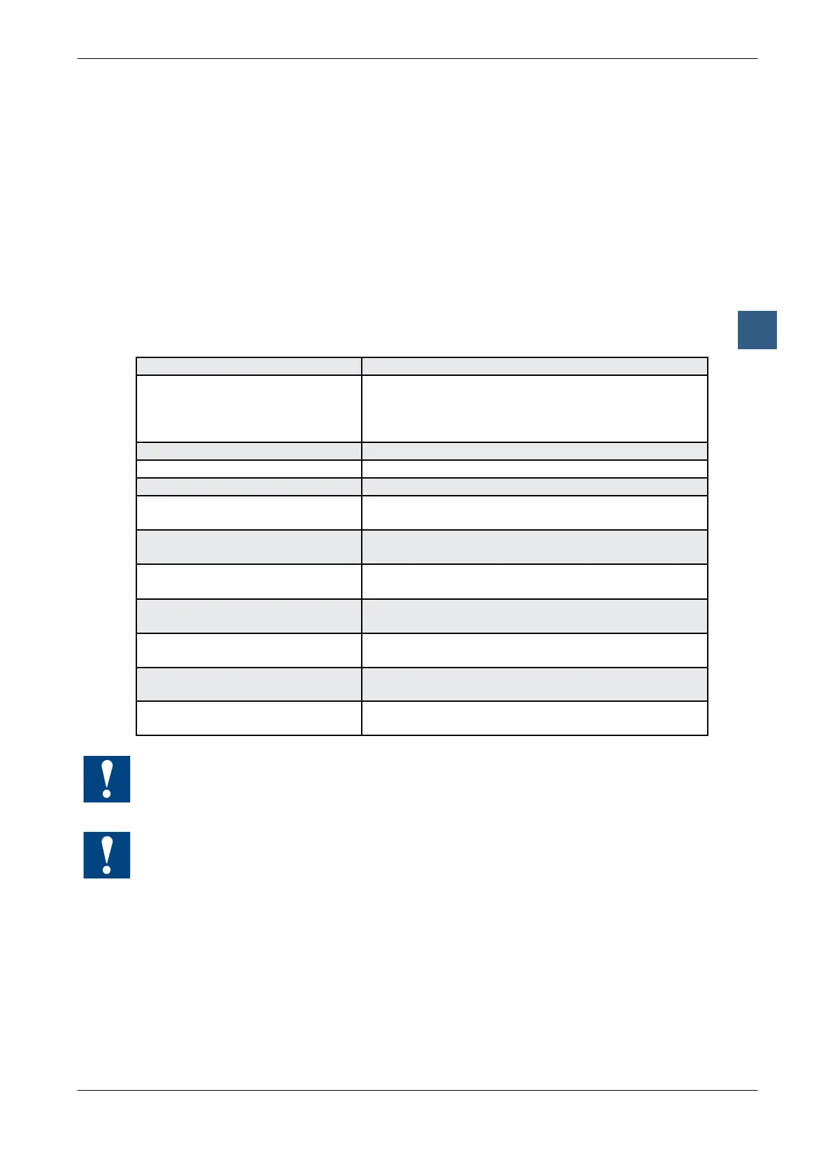
5.10.2 PCD2.W6x0, analogue outputs, 4 channels, 12 bit resolution
Application
High-speed output module for general use with 4 channels, each with 12 bit
resolution. Different variants for voltage 0 … 10 V, -10 … +10 V and current 0 … 20 mA
are available.
Module overview
PCD2.W600: Unipolar voltage outputs 0 … 10 V
PCD2.W610: Bipolar voltage outputs -10 V … +10 V, switchable
to unipolar voltage 0 … 10 V / current 0 … 20 mA
Technical data resolution
Number of output channels: 4, short circuit protected
Signal range: W600: 0 … +10 V 2.442 mV
W610: -10 V … +10 V 4.884 mV selectable
0 … +10 V 2.442 mV with
0 … 20 mA 4.884 μA jumper
Galvanic separation: no
Resolution (digital representation): 12 bits (0 … 4095)
Conversion time D/A: typ. 10 µs
Load impedance Voltage: > 3 kΩ
Current: < 500 Ω
Accuracy at 25 °C (of output value) Voltage: ± 0.5 %
Current: ± 0.8 % *)
Temperature error: Voltage: ± 0.1 %
Current: ± 0.2 %
(across temperature range
0 … +55 °C)
Internal current consumption:
(from +5 V bus)
W600: max. 4 mA
W610: max. 110 mA
Internal current consumption:
(from V+ bus)
W600: max. 20 mA
W610: 0 mA
External current consumption: max. 100 mA (type PCD2.W610 only, for current
outputs)
Terminals: Pluggable 10-pole screw terminal block
(4 405 4847 0), for wires up to 1.5 mm²
*) Note on current outputs:
Since for some applications it is important to be able to reach the outside limit
values of the range (0 mA, 20 mA), current outputs have been laid out according to
the following characteristic line:
During the start, a voltage of 5 V will be at all outputs of the module PCD2.W600.
The starting phase lasts 40 ms, afterwards 0 V will be put to the outputs.
}