Saia-Burgess Controls AG
Manual Manual PCD 1 / PCD 2 Series │ Document 26 / 737 EN22 │ 2013-11-26
5
Input/output (I/O) modules
5-43
Digital combined input and output modules
5.6.1 PCD2.B100, 2 inputs + 2 outputs + 4 digital inputs/outputs (selectable)
Application
Economical combined input/output module with:
● 2 inputs 24 VDC/8 ms for source operation, electrically connected
● 2 transistor outputs 0.5 A/5 … 32 VDC, electrically connected, not short circuit
protected, and
● 4 combined inputs/outputs 24 VDC/8 ms or 0.5 A/5 … 32 VDC on common I/O
terminals.
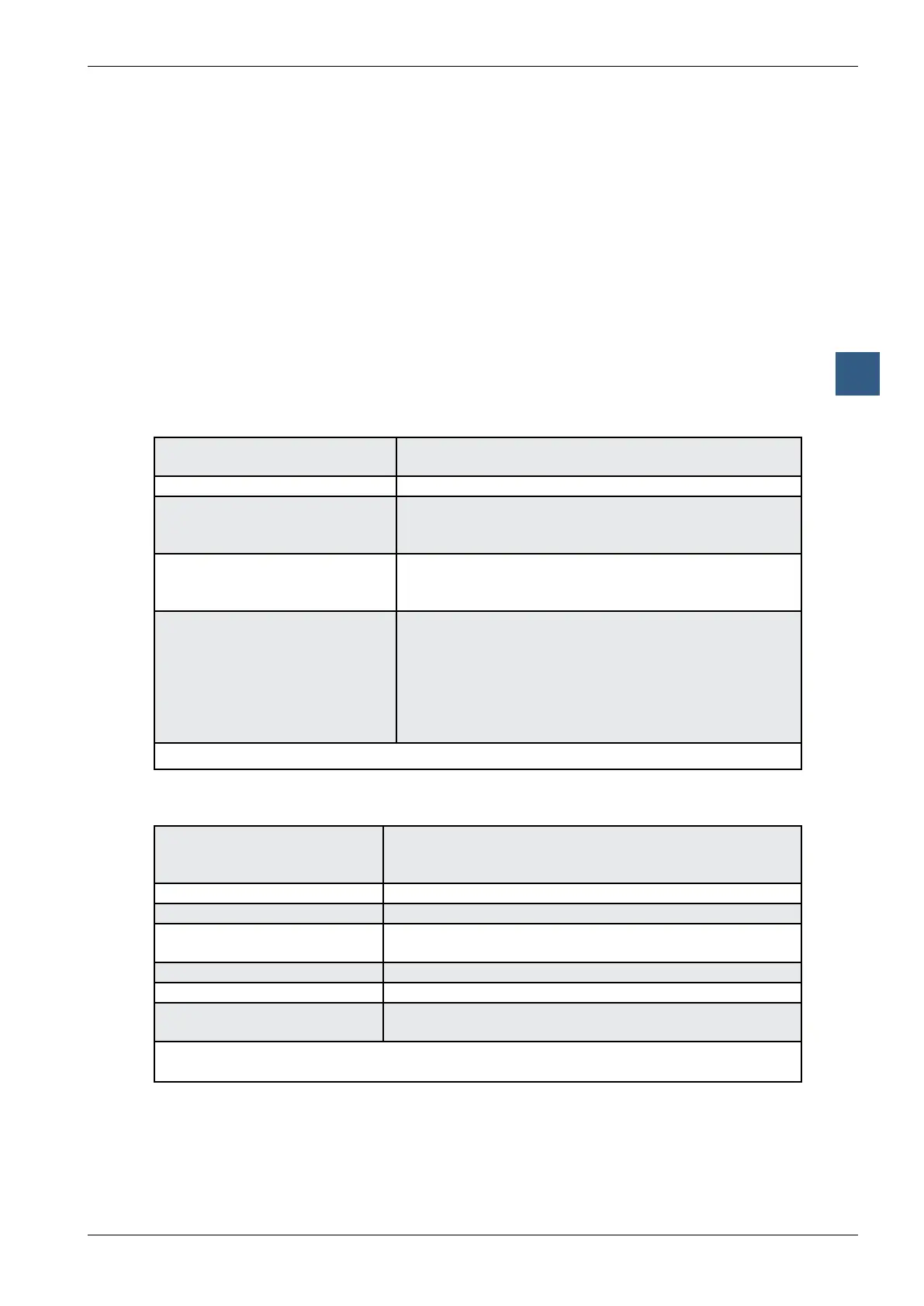
Technical data on inputs
Number of inputs: 6 (2 + 4), electrically connected,
source operation
Input voltage: 24 VDC smoothed or pulsed
2 inputs E0 and E1
low-range:
high-range:
-30 … +5 V
+15 … +32 V
4 inputs E/A2 … E/A5
low-range:
high-range:
-0.5 … +5 V *)
+15 … +32 V
All 6 inputs:
low-high switching threshold:
high-low switching threshold:
hysteresis:
input current (24 VDC):
switching delay 0-1 (24 VDC):
switching delay 1-0 (24 VDC):
13 V typically
6 V typically
7 V typically
7 mA typically
8 ms typically
8 ms typically
*) Negative voltage is restricted by the protective diode (I
max
= 0.5 A)
Technical data on outputs
Number of outputs: 6 (2 + 4) electrically connected,
source operation
not short circuit protected
Current: 5 … 500 mA steady load
Voltage range: 5 … 32 VDC *)
Voltage drop: < 0.3 V at 500 mA for A6 and A7
< 0.7 V at 500 mA for E/A2 … E/A5
Total current per module: 3 A steady load
Switch-on delay: 10 µs typically
Switch-off delay: 50 µs typically (100 µs max.), (ohmic load 5 … 500 mA),
longer for inductive load because of protective diode.
*) If it is intended to read the status of a combined output, the external voltage must be at
least 17 VDC, as both the status and the LED are displayed via the input.