Saia-Burgess Controls AG
Manual Manual PCD 1 / PCD 2 Series │ Document 26 / 737 EN22 │ 2013-11-26
4
Communication interfaces
4-25
Serial interfaces: socket B(1) or B2
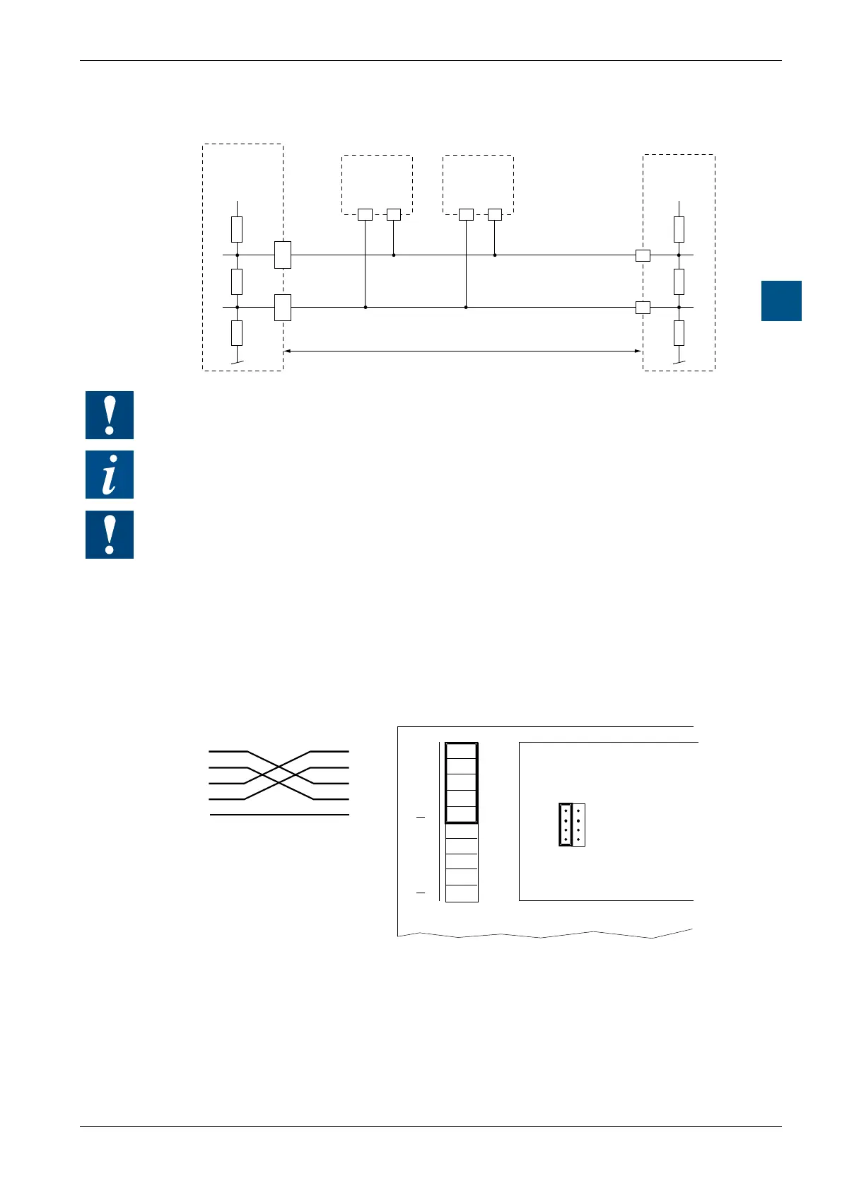
Connection diagram for RS-485 line termination resistors
+5 V
/RX-/TX
RX-TX
PCD1.M1xx
PCD2.Mxx0
PCD1.M1xx
PCD2.Mxx0
PCD1.M1xx
PCD2.Mxx0
+5 V
37/
47
/n
36/
46
n /n n
/n
n
PCD2.Mxxx
socket B(1), B2
Pull up
330 Ohm
Pull down
330 Ohm
Segment lenght max. 1200 m
max. 32 stations
Termination
Resistor
150 Ohm
At the rst and last stations, jumper J1 must be set to the “CLOSED“ position.
At all other stations, jumper J1 must be set to “OPEN” (factory setting)
For installation details, see manual 26 / 740 “Installation components for RS-485
networks”
The PCD7.F772 Probus module (details in 4.8.3) and the PCD7.F802 LON module
(details in 4.9) also have an RS-485 interface.
However, these modules are not supported by all PCD1 / PCD2 units.
The wiring is identical to the RS-485 wiring for the PCD2.F520 Modules.
4.7.2 RS-422 with PCD2.F520
RS-422: socket B(1) Port #3
39
38
37
36
35
34
33
32
31
30
PGND
TX
/TX
RX
/RX
SGND
TX
/TX
RX
/RX
J1
OPEN
CLOSED
39
38
37
36
34
33
32
31
PCD2.F520
Port # 2
RS-232
Port # 3
RS-422
Peripheral Cable
terminal block,
socket B/B1
Socket B(1)