Saia-Burgess Controls AG
Manual Manual PCD 1 / PCD 2 Series │ Document 26 / 737 EN22 │ 2013-11-26
Guidance
2-2
PlanninganapplicationwithPCD1/2/3components
2
2.2 Planning an application with PCD1/2/3 components
ThefollowingaspectsshouldbeconsideredwhenplanningPCD1/2applications:
● TheinternalloadcurrenttakenbytheI/Omodulesfromthe+5VandV+supply
mustnotexceedthemaximumsupplycurrentspeciedfortheCPUs
● TheCPUtypedeterminesthemaximumnumberofmodules
● ThetotallengthoftheI/Obusislimitedbytechnicalfactors;theshorter,thebetter
When planning an application, we recommend the following procedure:
SelecttheI/Omodulesaccordingtorequirements.
Checkthatthenumberofmodulesisallowed:
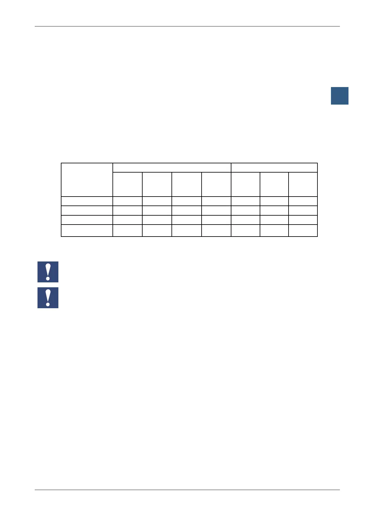
PCD
Type
Max.numberofI/Omodules Max.number¹)ofdigitalI/Os
PCD1/
PCD2
CPU
PCD2
expan-
sion
PCD3
expan-
sion
Total PCD1/
PCD2
CPU
Expan-
sion
Total
PCD1 4 – – 4 64 – 64
PCD2.M120/150 8 8 8 16 128 128(-1) 256(-1)
PCD2.M170 8 8 24 32 128 384(-2) 512(-2)
PCD2.M480 8 8 56 64 128 896(-1) 1024(-1)
¹)PCD2modulesandPCD3moduleswith16I/Oseach
Thevaluesinbracketshavetobesubtractedfromthemaximumnumberofdigital
I/Osbecauseofthewatchdogrelay.
IfyouwanttoexpandPCD2CPUswithPCD3LIOs/RIOs,pleaserefertothe
planninginstructionsinthePCD3manual.
Ifthenumberofmodulesisallowed,continuefrom;ifnot,selectadifferentCPU
Ifnecessary,selectthePCD2expansionhousing:
● PCD2.C100 with8modulesockets
● PCD2.C150 with4modulesockets
● PCD2.K100 26-coreextensioncableforconnectingPCD2baseunits
mountedbeneatheachother.
● PCD2.K110 26-coreextensioncableforconnectingPCD2baseunits
mountedside-by-side.
● PCD2.K120 26-coreextensioncableforspecicapplications(length2m).
● PCD2.K106 26-coreextensioncableforconnectingPCD2CPUswith
PCD3moduleholders.
WherePCD2.WxxxandPCD2.Hxxxmodulesareused,calculatetheload
currentfromtheinternal+5VandV+supply(usetheworst-case/highest
values)