Saia-Burgess Controls AG
Manual Manual PCD 1 / PCD 2 Series │ Document 26 / 737 EN22 │ 2013-11-26
CPUs and expansion housings
3-64
Interruptinputs
3
3.21 Interrupt inputs
3.21.1 Basics
Becauseoftheinputltersandtheeffectofthecycletime,thedigitalinputmodules
are not suitable for immediate reaction to events or for rapid counting processes.
Some CPUs have interrupt inputs for this purpose.
Whenapositiveedgeisdetectedattheinterruptinput,anassociatedXOBiscalled
(e.g.XOB20).ThecodeinthisXOBdeneshowtheunitshouldreacttotheevent,
e.g. by incrementing a counter.
The code in XOBs called from interrupt inputs must be kept as brief as possible to al-
low enough time between the interrupts to process the rest of the user program.
Many FBoxes are intended for cyclic invocation and so not suitable for use in XOBs,
or only in a limited way.
Exception:theFBoxesintheGraftecfamily(standardlibrary)arewellsuited
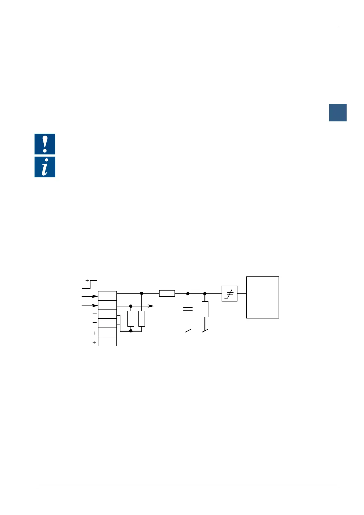
3.21.2 PCD1.M120/M130 and PCD1.M125/M135
The two interrupt inputs are located on the motherboard and can be connected via
the 6-pole, plug-in terminal block (terminals 20 to 25). Source operation is always
used.
Whenapositiveedgeisdetectedatinput INB1, XOB 20 is called; a positive edge at
input INB2 causes XOB 25 to be called. The reaction time up to the XOB 20/25 call
isamaximumof1ms.ThecodeinthisXOBdeneshowtheunitshouldreactto
theevent,e.g.byincrementingacounter(inputfrequencymax.1kHzwherepulse/
pauseeach50%,totalofthetwofrequenciesmax.1kHz).IftherelevantXOBisnot
programmed,theERRORLEDisswitchedonorXOB 13 is called.
25
23
22
21
20
INB2
INB1
3.3 nF
4k7
µC
68340
Input signals: (always source operation with PCD1.M12x and PCD1.M13x):
H = 15.. 30 V
L = -30..+5 V or no connected