Saia-Burgess Controls AG
Manual Manual PCD 1 / PCD 2 Series │ Document 26 / 737 EN22 │ 2013-11-26
CPUs and expansion housings
3-14
CPU overview
3
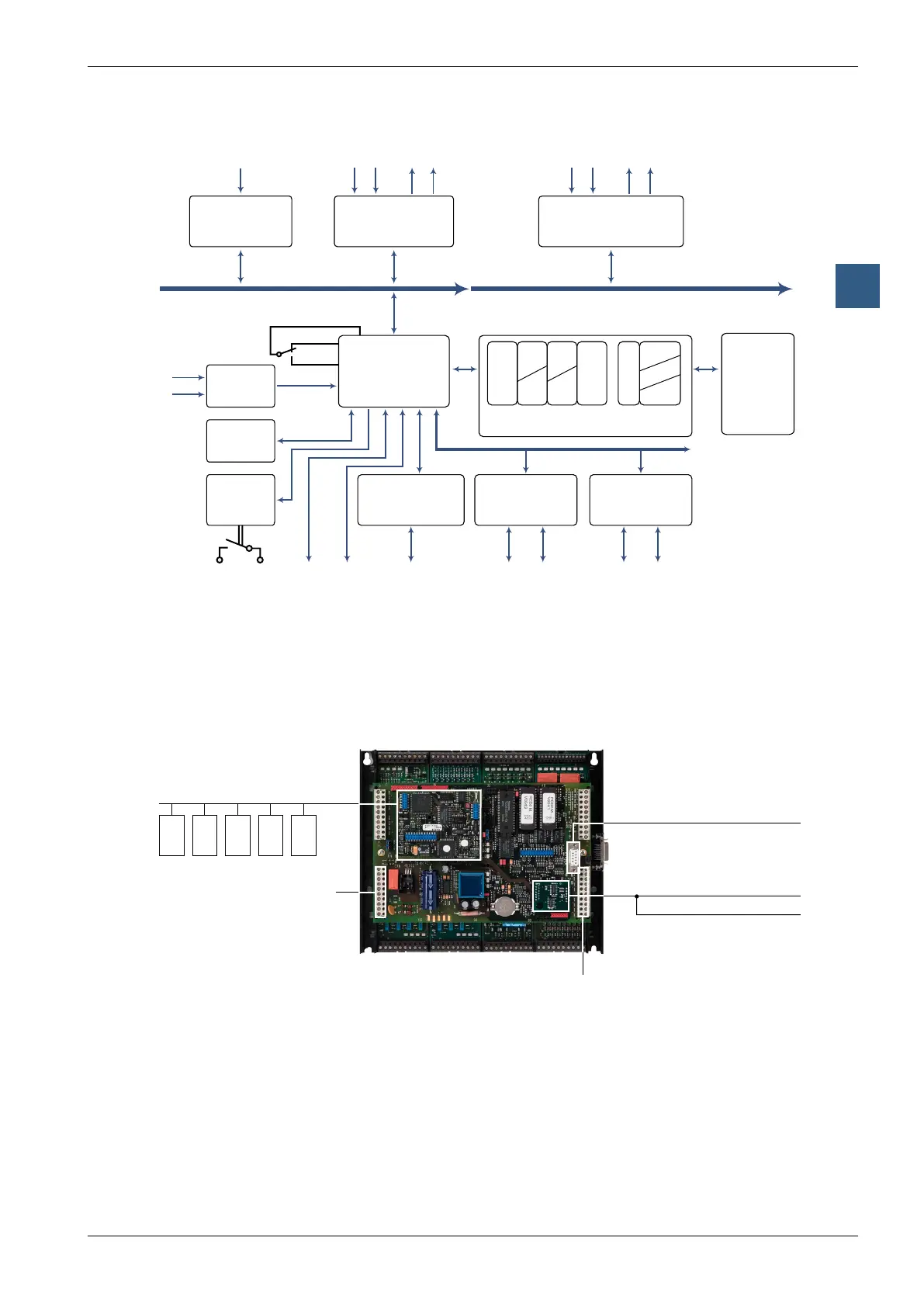
3.4.7 Block diagram : PCD2.Mxx0
Supply
I/O in extensions
adresses 128...
1
)
Socket B2
5
)
..F..-module
communications
RS-232/422/485
5
),
Profibus DP
5
)
6
),
LON
7
),
or Ethernet-TCP/IP
5
)
CPU
CPU- and I/O Bus
¹) PCD2.M110 is not expandable
2
) PGU: Connection for programming unit
3
) not with PCD2.M110
4
) not with PCD2.M170 and PCD2.M480
5
) only with PCD2.M170 and PCD2.M480
6
) only with PCD2.M150
7
) only with PCD2.M170
8
) only with PCD2.M480
9
) usable also as fast counter input (not with PCD2.M110)
M
e
m
o
r
y
m
a
p
E
E
P
R
O
M
DB
TX
P
T
vol
C
nvol
R
nvol
F
vol
F
nvol
PGU
2
)
ueser media
I/O Bus
user memory
register
timer
counter
flag
volatile
non volatile
program
text
data block
R
T
C
F
vol
nvol
P
TX
DB
Socket A
PCD7.F1xx-module
communications
I/O in base unit
adresses 0...127
USB
8
)
Datum-Time
nvol
HALT
5
)
Watch-Dog
Socket B(1)
..F..-module
communications
Backup
user
memory
..F..-module bus
RUN
5
)
Interrupt-
inputs
9
)
Serial
data interface
RS-232/422/485
3
),
Display
4
),
Profibus FMS
6
)
7
),
Profibus DP
5
)
6
),
LON
6
)
7
),
or Ethernet-TCP/IP
6
)
Socket A for serial
data port Port 1
Socket B for Profibus DP/FMS or
LonWorks
®
switching mode,
for serial data ports,
6-digit display, small terminal
Programmingunit(PGU)
or RS-232 serial data port (Port #0)
or telecommunications/SMS
viamodemmoduleonI/Osocket
Screw terminals for supply, watch-
dog and Port #0 as RS-485
PCD2.M110/M120/M150
B
A
Screw terminals Port 1