Saia-Burgess Controls AG
Manual Manual PCD 1 / PCD 2 Series │ Document 26 / 737 EN22 │ 2013-11-26
CPUs and expansion housings
3-65
Interruptinputs
3
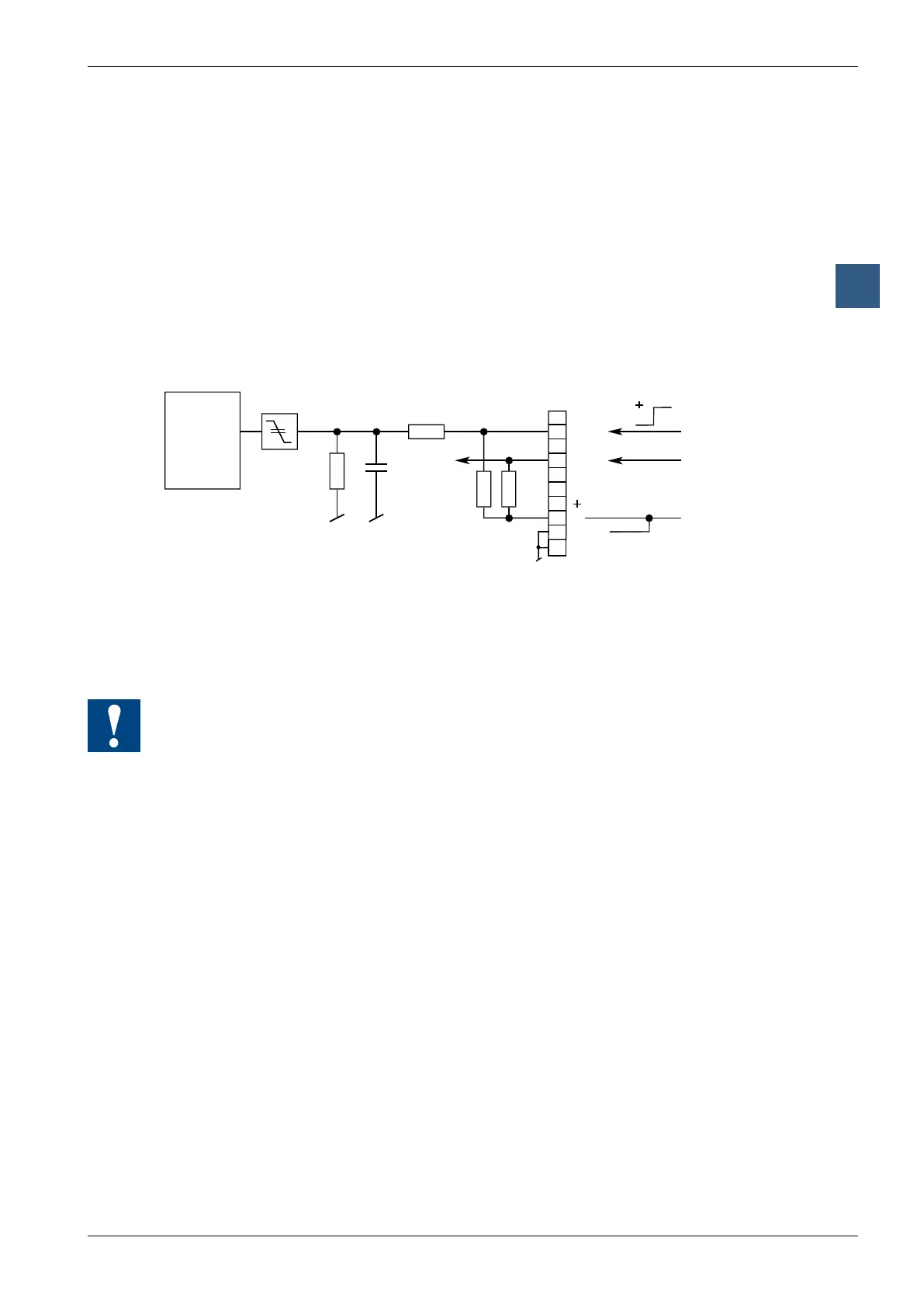
3.21.3 PCD2.M120/M150/M170
The two interrupt inputs are located on the motherboard and can be connected via
the10-pole,plug-interminalblock(terminals0to9).Eithersourceorsinkoperation
may be used.
Function in source and sink operation:
Whenapositiveedgeisdetectedatinput INB1, XOB 20 is called; a positive edge at
input INB2 causes XOB 25 to be called. The reaction time up to the XOB 20/25 call
isamaximumof1ms.ThecodeintheseXOBsdeneshowtheunitshouldreactto
theevent,e.g.byincrementingacounter(inputfrequencymax.1kHzwherepulse/
pause each 50 %,totalofthetwofrequenciesmax.1kHz).IftherelevantXOBisnot
programmed,theERRORLEDisswitchedonorXOB 13 is called.
Input signals (source operation):
H = 15.. 30 V
L = -30.. + 5 V or no connected
Input signals (sink operation):
H = 15 .. 30 V or no connected
L = -30.. + 5 V
source operation
(for sink operation
L at +24 V)
3.3 nF
TheINA1,INA2,OUT1,OUT2and+connectionsareintendedforfuture
enhancements and must not be used.
3.21.4 PCD2.M480
The four interrupt inputs are located on the motherboard and can be connected via
the10-pole,plug-interminalblock(terminals0to9).Eithersourceorsinkoperation
may be used.
Function in source and sink operation:
Each interrupt input is mapped to an XOB that will be called when there is a positive
edgeattheinput.ThecodeintheseXOBsdeneshowtheunitshouldreacttothe
event, e.g. by incrementing a counter (input frequency max.
1kHzwherepulse/pauseeach50 %).ThereactiontimeuptotheXOB20 … 23callis
a maximum of 1 ms.
IftherelevantXOBsarenotprogrammed,theinterruptinputscanbeusedintheuser
program like normal inputs from address 8100 upwards.