Saia-Burgess Controls AG
Manual Manual PCD 1 / PCD 2 Series │ Document 26 / 737 EN22 │ 2013-11-26
CPUs and expansion housings
3-33
PinCongurationPCD1
3
3.12 PinCongurationPCD1
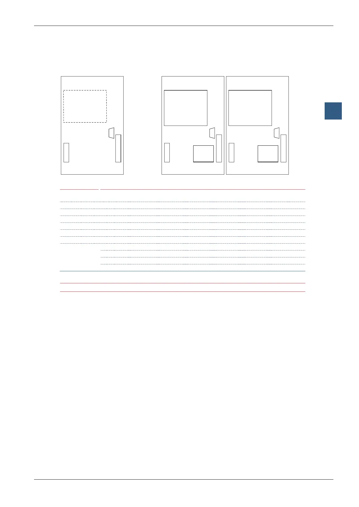
Situation of sockets and screw terminal blocks on PCD1
B
Profibus DP - Master/Slave
(PCD7.F750 / PCD7.F770)
LonWorks
®
(PCD7.F800)
25
20
10
19
PGU/RS-232
Port #0
Small Terminal (PCD7.D162)
A
Port #1
PCD1.M125
B
Profibus DP - Master/Slave
(PCD7.F750 / PCD7.F770)
LonWorks
®
(PCD7.F800),
Ethernet-TCP/IP (Ether-S-Bus)
(PCD7.F650),
25
20
10
19
PGU/RS-232
Port #0
Small Terminal (PCD7.D162)
A
Port #1
PCD1.M135
Small Terminal PCD7.D162
25
20
10
11
12
19
PGU/RS-232
Port #0
Port #1
PCD1.M110
RS-485
(on board)
Supply/Interrupts Optional serial data ports, socket A, Port #1 (Screw terminal block)
Pin
20…25
Signal Pin
10...19
RS-485
2)
PCD7.F110
RS-422
PCD7.F110
RS-232
PCD7.F120
TTY/20 mA
PCD7.F130
RS-485
3)
PCD7.F150
MP-Bus
PCD7.F180
20 +24V 10 PGND PGND PGND PGND PGND PGND
21 +24V 11 RX-TX TX TXD TS RX-TX MP
22 PGND 12 /RX-/TX /TX RXD RS /RX-/TX ‚MFT‘
23 PGND 13 – RX RTS TA – ‚IN‘
24 INB2
1
) 14 – /RX CTS RA – ‚GND‘
25 INB1
1
) 15 PGND PGND PGND PGND PGND PGND
16 – RTS DTR TC –
17 – /RTS DSR RC –
18 – CTS RSV TG SGND
19 – /CTS DCD RG –
1)
Not valid for the PCD1.M110
2)
Also valid for the built-in RS-485 interface of PCD1.M110
3)
galvanically isolated
PGU/RS-232,Port#0seetablePCD2
Moduls at socket B
ProbusDPandLonWorks
®
The bus should be connected directly to the PCD7.F7x0 module.
Connection can be achieved via screw terminal blocks. For details see manuals 26/737, 26/742, 26/765,
26/767
Ethernet-TCP/IPmodule
Ethernet-TCP/IPasconguredsystemPCD1.M135F655(withspecialcoverno.410474090).
Connection can be achieved via RJ 45 plug of category 5. For details see manual 26/776