Saia-Burgess Controls AG
Manual Manual PCD 1 / PCD 2 Series │ Document 26 / 737 EN22 │ 2013-11-26
4
Communication interfaces
4-9
Onboard interfaces
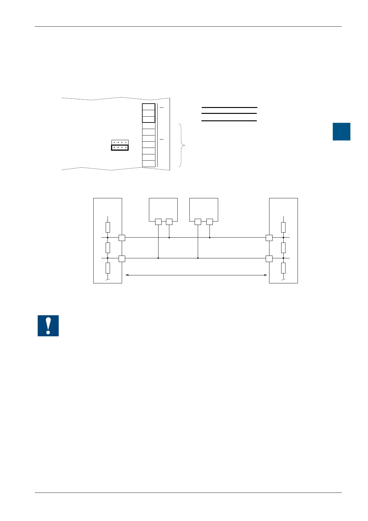
4.5.4 RS-485 communication interface PORT # 1, only on PCD1.M110
On the PCD1.M110, on Port #1, is a built-in RS-485 interface.
OPEN
CLOSED
GND
Bus RS-485
not used
Bus-cable
terminal-
block A
Bus RS-485
PCD1.M110
Choice of the termination resistors
+5 V
PCD1.M110
Port #1
PCD1.M1xx
PCD2.Mxx0
PCD1.M1xx
PCD2.Mxx0
PCD1.M1xx
PCD2.Mxx0
/RX - /TX
n n
11 n
/n
/n/n
12
RX - TX
+5 V
Pull up
330 Ohm
Termination
Resistor
150 Ohm
Segment length max. 1200 m
max. 32 stations
Bus-RS485
First station Middle stations End station
Pull down
330 Ohm
At the rst and last stations, the jumper must be set to the “CLOSED“ position.
At all other stations, the jumper must be set to “OPEN” (factory setting).