Saia-Burgess Controls AG
Manual Manual PCD 1 / PCD 2 Series │ Document 26 / 737 EN22 │ 2013-11-26
CPUs and expansion housings
3-25
InstallationandaddressingofPCD2I/Omodules
3
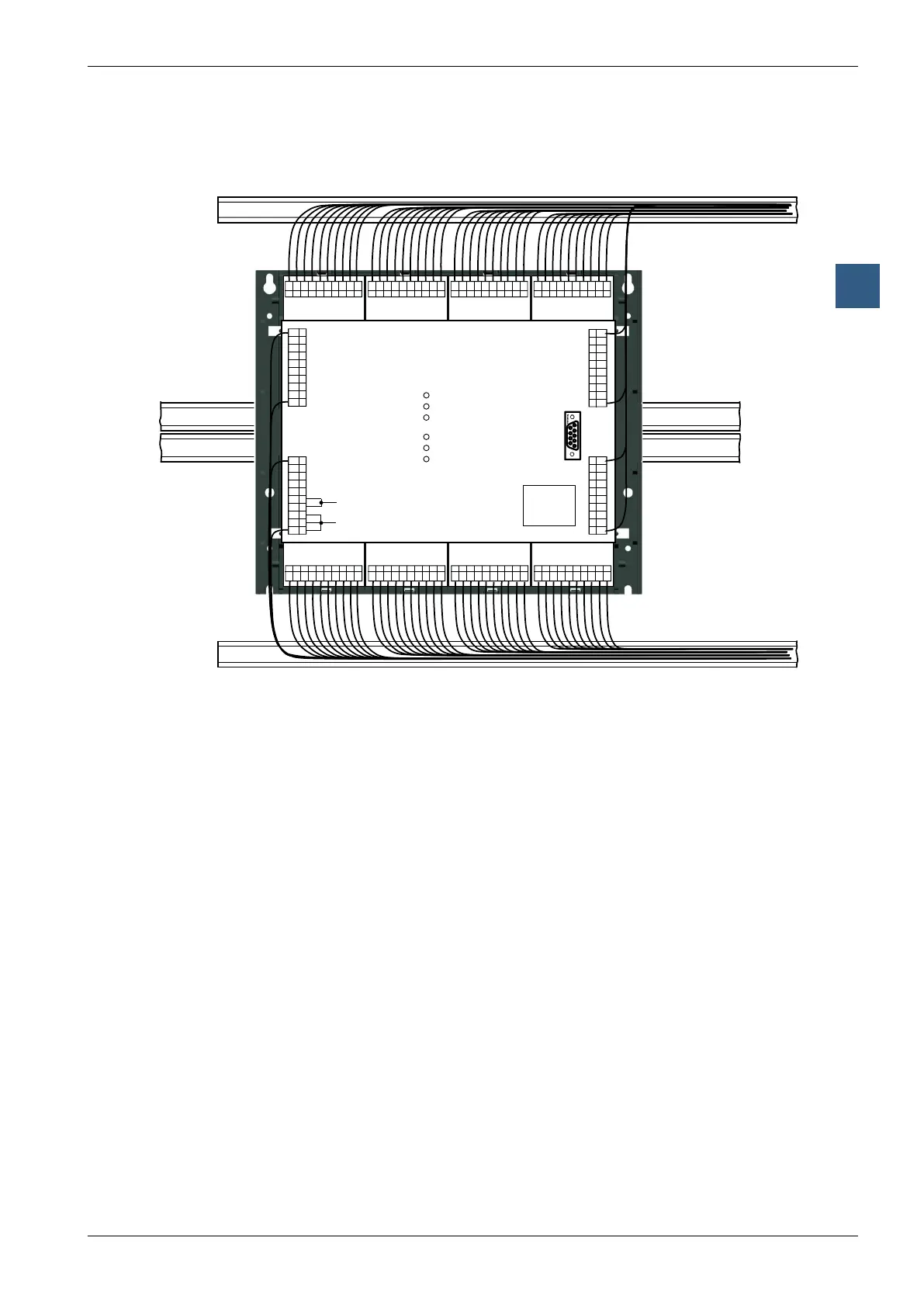
3.7.3 Cable layout
WiringtotheI/Omodulescanbelaidinthecablechannelsonbothsides.
AxxxAxxxWxxxWxxx
AxxxAxxxExxxExxx
F1xx
PGU
24 VDC
Battery
WD
Run
Halt
Error
CPU
Interrupt
Supply
_
_
_
_
+
+
+
The cables to the terminals on the motherboard are run through the two side chan-
nels from the bottom or from the top.
On the PCD2.M170 and the PCD2.M480, the terminals on the motherboard are ac-
cessible without removing the cover.
FollowingtheseruleswillensurethattheLEDsarevisibleandthebusconnections
remain accessible.