Saia-Burgess Controls AG
Manual Manual PCD 1 / PCD 2 Series │ Document 26 / 737 EN22 │ 2013-11-26
4
Communication interfaces
4-8
Onboard interfaces
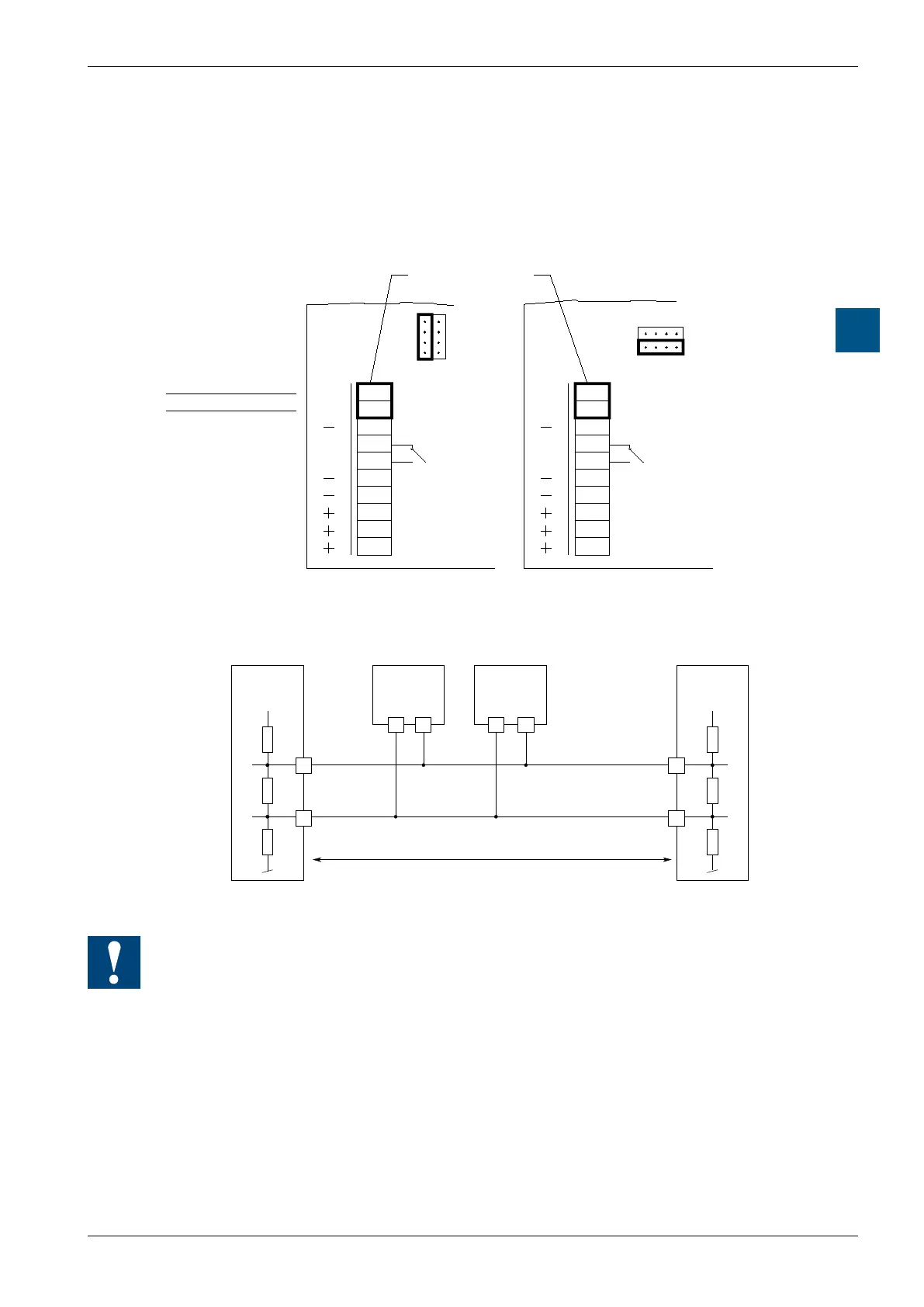
4.5.3 PGU connection (PORT # 0, only on PCD2.M1x0) (RS-485)
as communication interface
If Port #0 is not used via the PGU connection (with the programming device or as
an RS-232 interface), it can be used via terminals 28 and 29 for an S-Bus or MC4
connection.
29
27
26
25
24
23
22
21
20
D
/D
WD
WD
J0
OPEN
CLOSED
PCD2.M110
PCD2.M120
PCD2.M150
RX - TX
/RX - /TX
28
RS-485
Bus-cable
Screw terminal block
29
27
26
25
24
23
22
21
20
D
/D
WD
WD
J0
OPEN
CLOSED
PCD2.M170
28
Choice of line termination resistors
+5 V
/RX - /TX
n n
29 n
/n
/n/n
28
RX - TX
PCD2.M1x0
Port #0
PCD1.M1xx
PCD2.Mxx0
PCD1.M1xx
PCD2.Mxx0
PCD1.M1xx
PCD2.Mxx0
+5 V
Pull up
330 Ohm
Termination
Resistor
150 Ohm
Segment length max. 1200 m
max. 32 stations
Bus RS-485
First station Middle stations End station
Pull down
330 Ohm
At the rst and last stations, jumper J0 must be set to the “CLOSED“ position.
At all other stations, jumper J0 must be set to “OPEN” (factory setting).