Saia-Burgess Controls AG
Manual Manual PCD 1 / PCD 2 Series │ Document 26 / 737 EN22 │ 2013-11-26
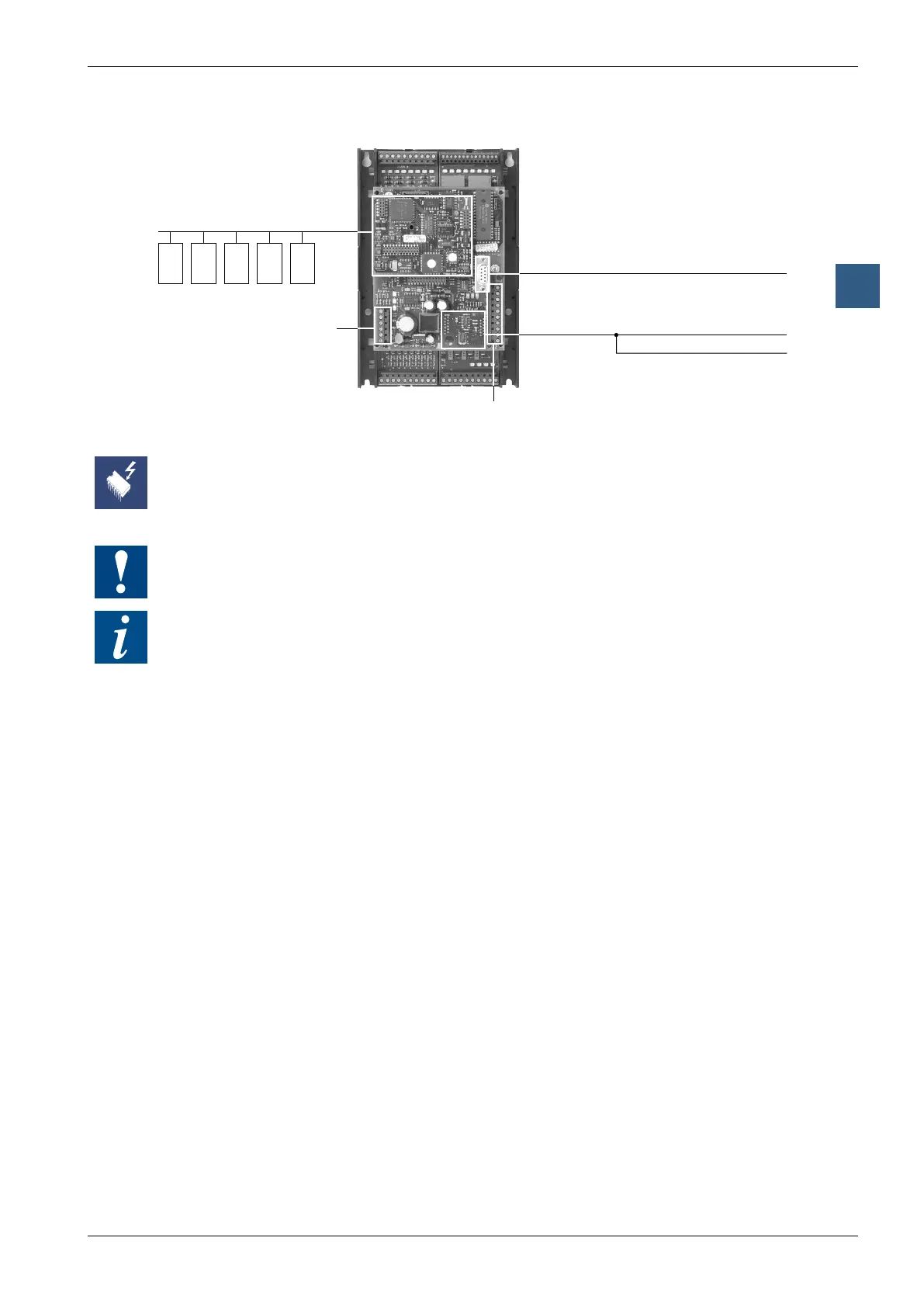
CPUs and expansion housings
3-9
CPU overview
3
B
A
Socket B for Profibus DP or
LonWorks
®
switching modes,
EthernetTCP/IP,smallterminal
(PCD1.M110, small terminal only)
Socket A for serial data port Port 1
(PCD1.M110 fixed RS-422/485); on the PCD1.
M120/M125/M130/M135, a PCD7.F1xx module
can be plugged in
or telecommunications/SMS
viamodemmoduleonI/Osocket
Programmingunit(PGU)
or RS-232 serial data port (Port #0)
PCD1.M1x0
Screw terminals for interrupt
inputs and supply,
terminals 20 (bottom) to 25 (top)
Screw terminals Port 1,
terminals10(top)to19(bottom)
Removing the cover exposes components that are sensitive to electrostatic discharges.
Recommendations: Immediatelybeforetouchingtheelectroniccircuits,brieytouchthe
metalhousingofthePGUconnection.Itissafertouseananti-staticwristband,connected
to the Minus of the system.
I/OmodulesandI/Oterminalblocksmayonlybepluggedinandremovedwhenthe
Saia PCD
®
and the external +24 V are disconnected from the power supply.
Removing the cover exposes components that are sensitive to electrostatic discharges.
3.4.3 HardwareandrmwareversionsforthePCD1
ThermwareversionsforthePCD1.M1xxaregenerallyupwardlycompatibleinterms
ofhardware,sooldCPUscanbettedwithnewrmware,inordertotakeadvantage
of new functions. This feature is highly valued, and we will try to retain it for as long
as possible; however, we cannot guarantee this.
At this point, the following known restrictions apply:
● TheuseofintelligentcommunicationmodulessuchasProfibusDP,LONandEth-
ernet requires the minimum hardware and firmware versions. Please refer to the
manuals for the relevant communication modules