Saia-Burgess Controls AG
Manual Manual PCD 1 / PCD 2 Series │ Document 26 / 737 EN22 │ 2013-11-26
CPUs and expansion housings
3-62
InternalLEDdisplaysandsmallterminals
3
In-
struc-
tion
Display Mode after
instruction
DSP K 22
3)
Switch to free mode in 2-digit mode 2-digit
1) TheseinstructionsmustbefollowedbyasecondDSPinstructionintheformat:DSPRx;x=0..4095.The
registervaluemustbe0..99.Ifthevalueisoutsidethisrange,nothingwillbedisplayedandtheerrorflagwillbe
set
2) On the PCD2.M110/M120, available from firmware version 002 only
3) On the PCD2.M110/M120, available from firmware version 003 only
The effect of the DSP R x instruction is dependent on the mode of the 7-segment
display:
Mode Content of R x Effect of DSP R x instruction
6-digit -99,999to
+999,999
outside this
range
Thevalueintheregisterisdisplayedright-justied.Only
integer values in decimal format can be displayed
nodisplay;theerroragisset
2-digit 0to99
outside this
range
The value is displayed in the two rightmost digits. The four
digits to the left of these are unchanged
Nodisplay;theerroragisset
Free
mode
0 to 11111111
binary or
0 to 255
decimal
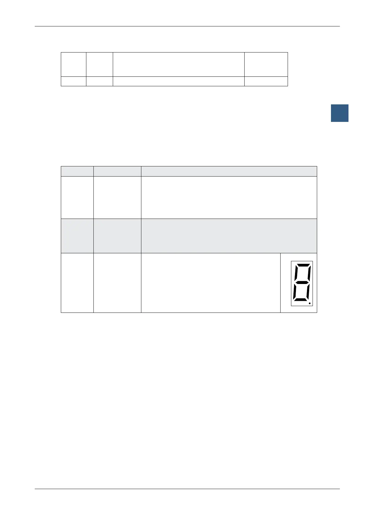
The segments of the rightmost digit are set
according to the following layout:
(Bit 0 = lowest value bit)
Example: R x is binary 01110101; a 3 is displayed
with no decimal point
0
1
2
3 4
5
6
7
3.20.3 PCD2.F530 7-Segment LED display (PCD2.M120/M150 only)
This module combines the 7-segment display of a PCD2.F510 (please refer to the
preceding section) and the two serial ports of a PCD2.F520 (details in section 3).