Saia-Burgess Controls AG
Manual Manual PCD 1 / PCD 2 Series │ Document 26 / 737 EN22 │ 2013-11-26
5
Input/output (I/O) modules
5-42
Digital combined input and output modules
5.6 Digital combined input and output modules
PCD2.B100 2 inputs, 2 outputs, 4 selectable as inputs or outputs
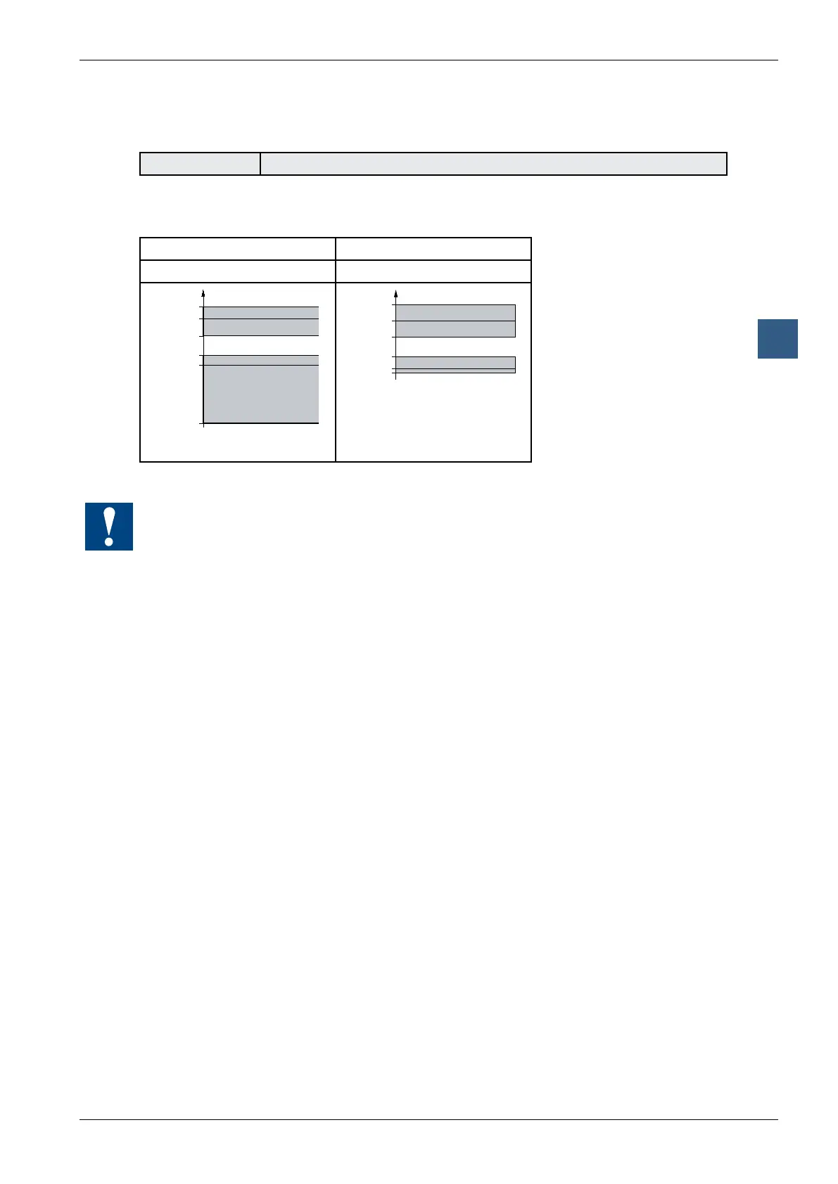
Denition of input signals
for 24 VDC for 24 VDC
PCD2.B100; E0 and E1 PCD2.B100; E2 to E5
32 V
DC
24 V
DC
15 V
DC
0 V
DC
5 V
DC
-30 V
DC
1
0
32 VDC
24 VDC
15 VDC
0 VDC
5 VDC
-0.5 VDC
1
0
I/O modules and I/O terminal blocks may only be plugged in and removed when the
Saia PCD
®
and the external +24 V are disconnected from the power supply.