Saia-Burgess Controls AG
Manual Manual PCD 1 / PCD 2 Series │ Document 26 / 737 EN22 │ 2013-11-26
4
Communication interfaces
4-36
Probus
4.9.2 Probus DP Slave, module PCD7.F77x
PCD1.M120 / M130 and PCD2.M120 / M150
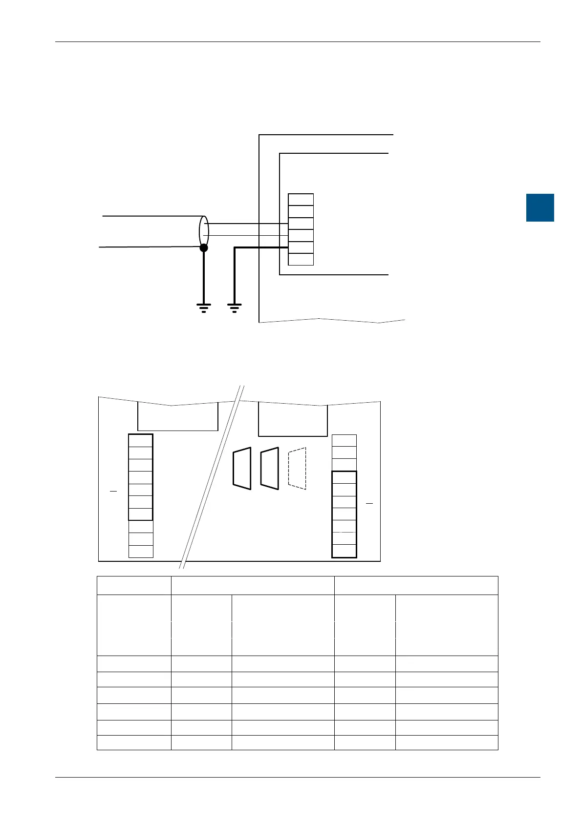
The bus should be connected directly to the module PCD7.F770 or PCD7.F772.
PCD7.F77x
PCD7.F770 with PCD2.M170
The bus should be connected to the D-Sub connector. The pin conguration is as per
the Probus standard. Alternatively the Probus can be attached to the screw termi-
nal block.
Profibus DP Master
PCD2.M170
PCD7.F77x
PCD7.F77x
B2
B1
B1 B2
#0#8#9
PGU
39
38
37
36
35
34
33
32
31
30
39
38
37
36
34
33
40
41
42
43
44
45
46
47
48
49
43
44
46
47
48
49
Port #9
Port #8
Socket B1 Port #9 B2 Port #8
Kind of con-
nection
D-Sub Screw terminal block D-Sub Screw terminal block
9 pole 10 pole 9 pole 10 pole
Signal Pin number Terminal number Pin number Terminal number
RTS / CNTR-P 4 33 4 43
PGND 1 35 1 45
RxD / TxD-N 8 36 8 46
RxD / TxD-P 3 37 3 47
DP GND 5 38 5 48
DP +5 V 6 39 6 49