Saia-Burgess Controls AG
Manual Manual PCD 1 / PCD 2 Series │ Document 26 / 737 EN22 │ 2013-11-26
4
Communication interfaces
4-48
MP-Bus PCD2.T500
Total power consumption of MFT2 actuators [W]
1
10
100
1000
10 000
01020304050607090100 [W]
80
0.75 mm
2
1.0 mm
2
1.5 mm
2
2.5 mm
2
Kabellänge [m]
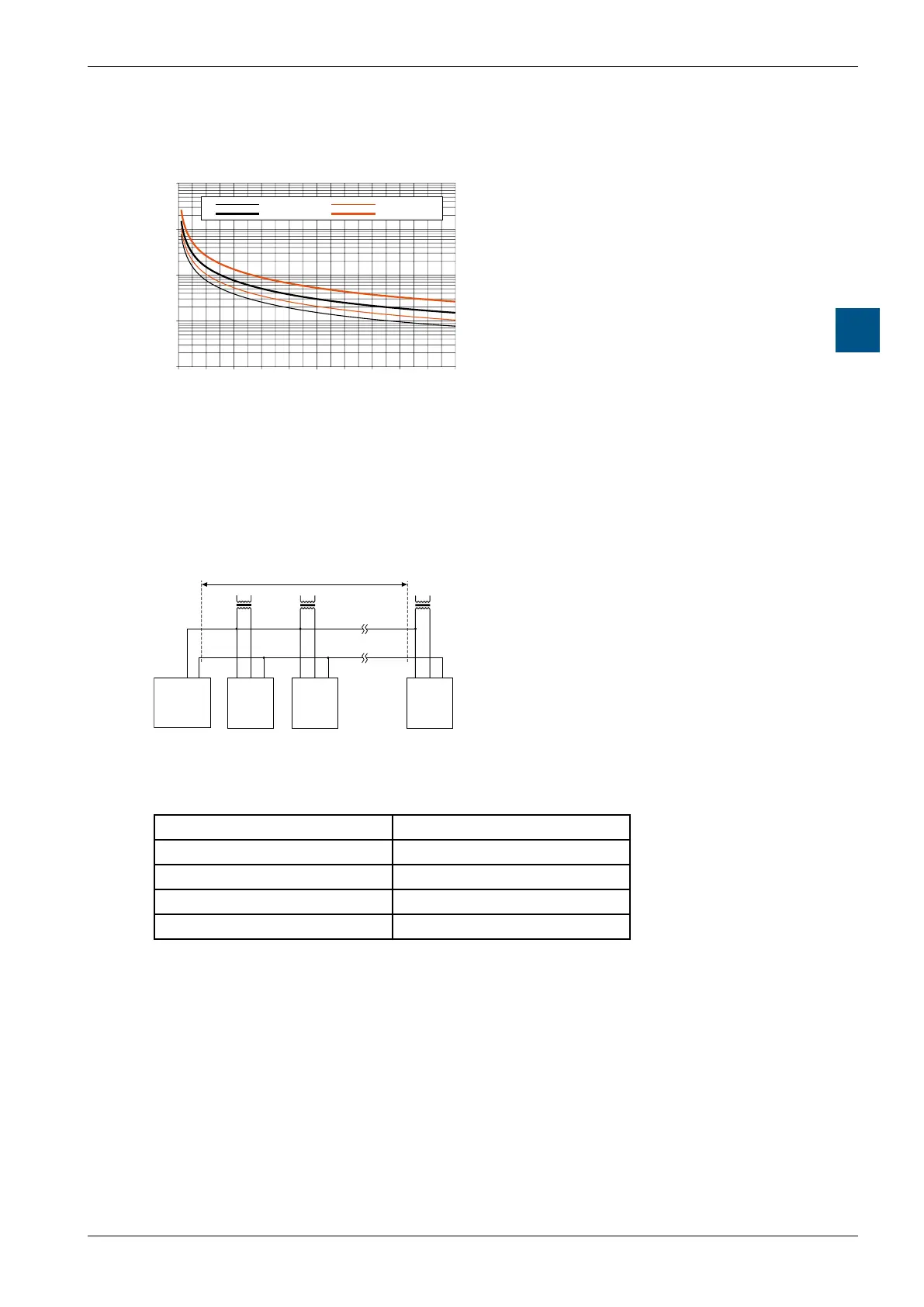
Cable length vs true watts applies to DC supply
(minimum supply voltage 24.0 VDC)
The following can be read from the family of curves:
– Cable with conductor 0.75 mm² gives: Cable length 60 m
– Cable with conductor 1.0 mm² gives: Cable length 80 m
– Cable with conductor 1.5 mm² gives: Cable length 115 m
– Cable with conductor 2.5 mm² gives: Cable length 200 m
4.11.10 Maximum line length for 24 VAC supply (in situ)
1 2 5 1 2 5 1 2 5
6 4/5
Masse
MP
PCD2.T500
Maximum line length for 24 VDC supply
24 VAC
Drive
1
Drive
2
Drive
8
24 VAC
24 VAC
If the actuators are supplied locally with 24 VAC via a separate transformer, line
lengths can be much increased. Regardless of the power ratings for the actuators
connected, the line lengths will be according to the following table.
Conductor Ø L = max. line length
0.75 mm² 800 m
1.0 mm² 800 m
1.5 mm² 800 m
2.5 mm² 800 m