Saia-Burgess Controls AG
Manual Manual PCD 1 / PCD 2 Series │ Document 26 / 737 EN22 │ 2013-11-26
CPUs and expansion housings
3-23
Expansion housings and bus cables
3
3.6.3 Expansion with PCD4 components
Starting from a PCD2.M120/M150/M170/M480, the PCD4.C225 coupling bus module
makesitpossibletorunthefollowingI/Omodulesandmanualcontrolmodulesfrom
the PCD4 series:
Digital input/output modules Manual control modules
PCD4.E11x PCD4.A810
PCD4.E60 PCD4.A820
PCD4.A200
PCD4.A250
PCD4.A350
PCD4.A400
PCD4.A410
PCD4.B90x
AnyPCD4I/Omodulesnotlistedarenotsupported.
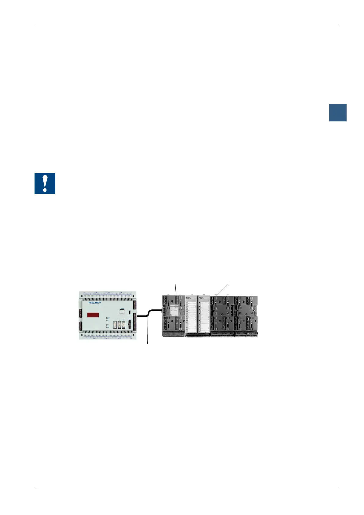
As shown in the illustration below, the PCD4.C225 is connected to the PCD2 via a
PCD2.K100/K110/K120 extension cable.
Using standard PCD4.C220 or PCD4.C260 bus modules, up to 6 additional module
sockets can be attached to the right-hand side of the PCD4.C225 coupling bus
module (making a total of 8 PCD4 sockets).
Itisnecessarytoensurethattheinternal5Vand+VsupplyforthePCD2isnot
overloaded. The power consumption for the PCD4 modules can be found in manual
26/734.
PCD2.M120/M150/M170/M480
PCD4.C220/C260PCD4.C225