Saia-Burgess Controls AG
Manual Manual PCD 1 / PCD 2 Series │ Document 26 / 737 EN22 │ 2013-11-26
Appendix
A-2
Denitions of serial interfaces
A
A.2 Denitionsofserialinterfaces
A.2.1 RS-232
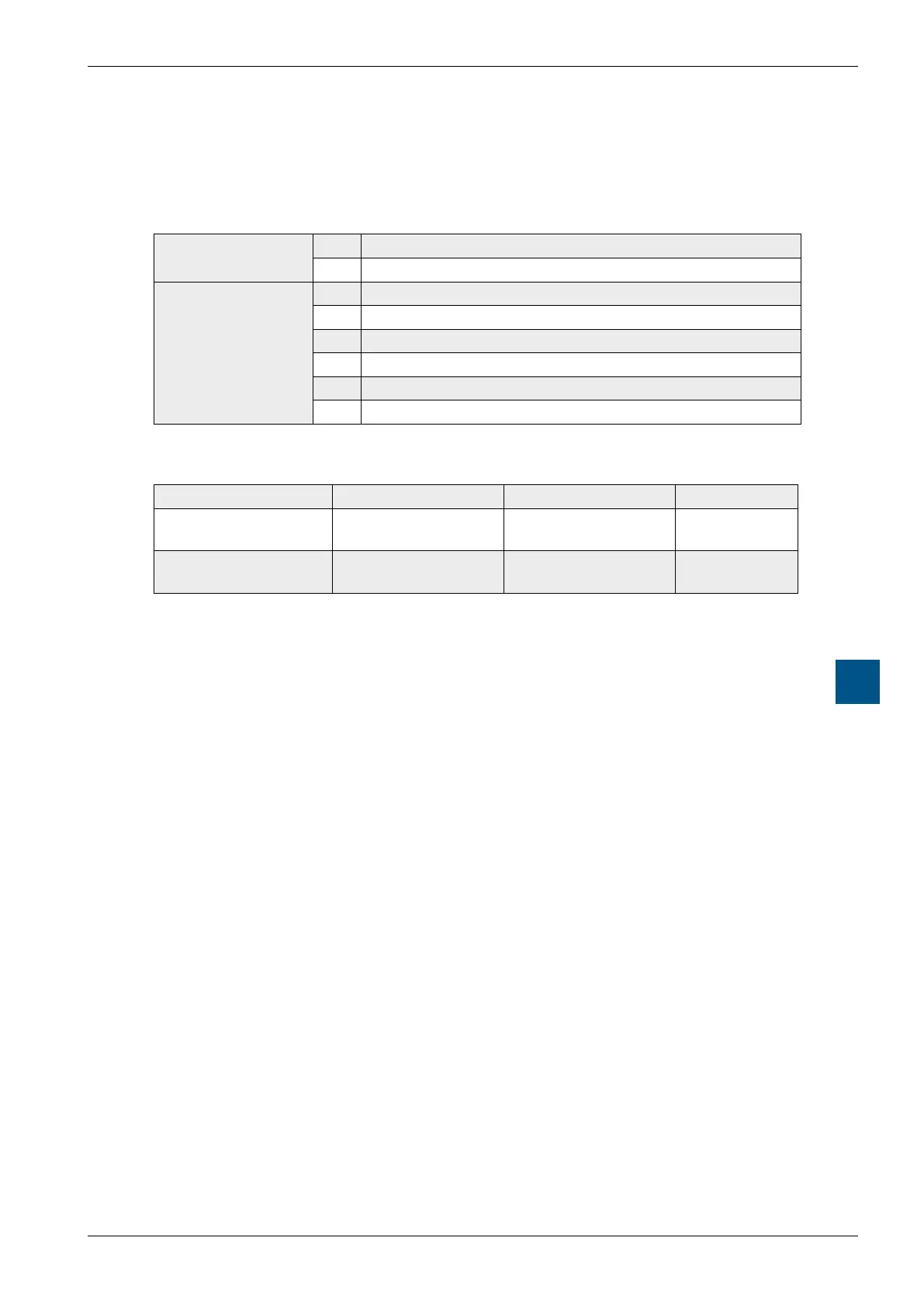
Designation of signal lines:
Data lines
TXD Transmit data
RXD Receive data
Signal and
response circuits
RTS Request to send
CTS Clear to send
DTR Data terminal ready
DSR Data set ready
RI Ring indicator
DCD Data carrier detect
Signals to RS-232
Signal type Logical state Required value Nominal value
Data signal 0 (space)
1 (mark)
+3 V to +15 V
-15 V to -3 V
+7 V
-7 V
Control /
message signal
0 (off)
1 (on)
-15 V to -3 V
+3 V to +15 V
-7 V
+7 V
The idle state of the data signals = “mark”
of the control and message signals = “off”