Saia-Burgess Controls AG
Manual Manual PCD 1 / PCD 2 Series │ Document 26 / 737 EN22 │ 2013-11-26
Appendix
A-3
Denitions of serial interfaces
A
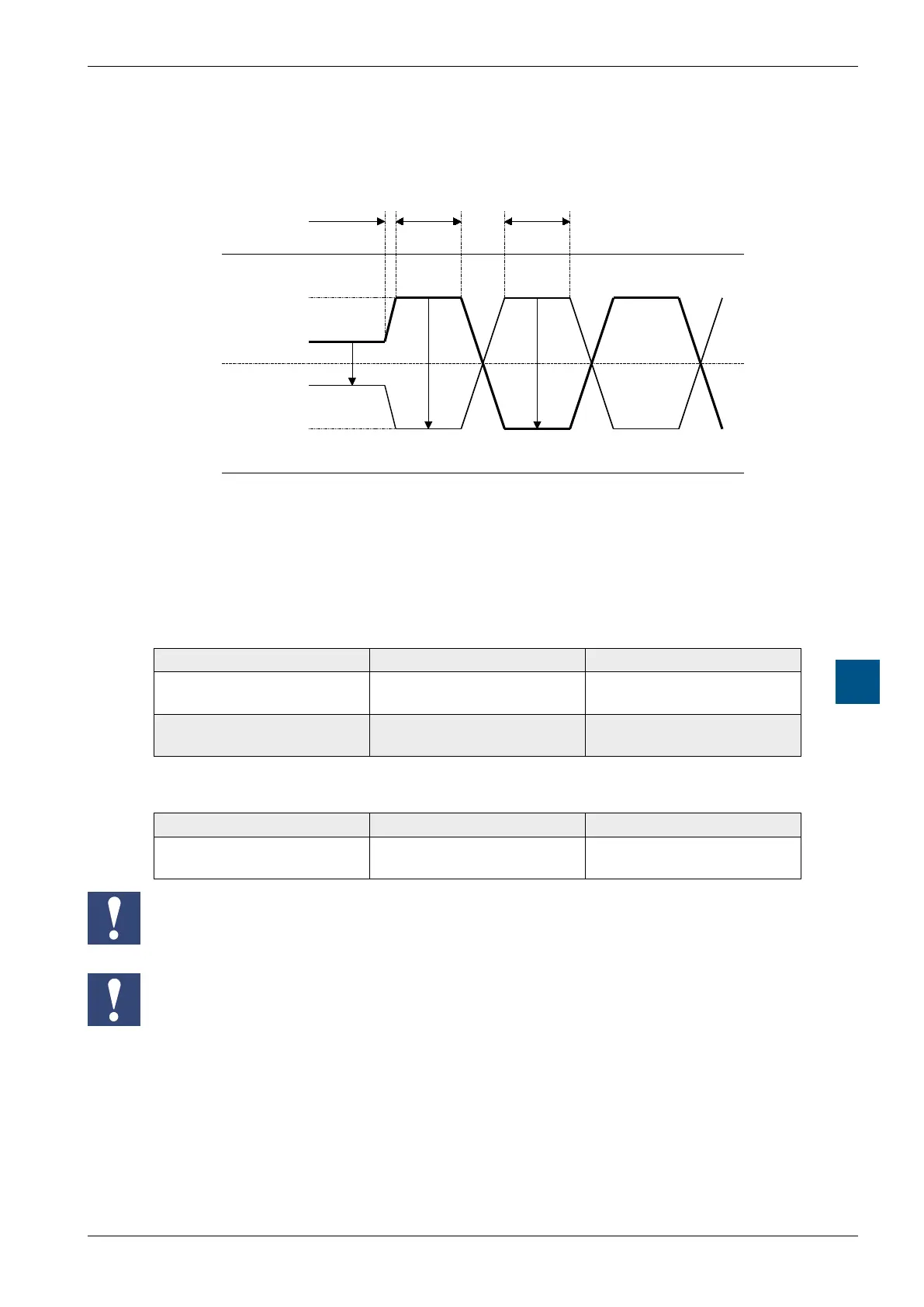
A.2.2 RS-485 / 422
Signals to RS-485 (RS-422)
5V
2.5V
0V
4V
3V
2V
1V
VOH
VOL
VOZ
/TX
TX
mark
space
= mark
not active
e.g. Startbit
VOZ = 0.9 V min … 1.7 V
VOH = 2 V min (with load) … 5 V max (without load)
VOL = -2 V … -5 V
In the idle state, RS-422 is in the “mark” position
RS-422:
Signal type Logical state Polarity
Data signal 0 (space)
1 (mark)
TX positive to / TX
/ TX positive to TX
Control /
message signal
0 (off)
1 (on)
/ RTS positive to RTS
RTS positive to / RTS
RS-485:
Signal type Logical state Polarity
Data signal 0 (space)
1 (mark)
RX-TX positive to / RX- / TX
/ RX- / TX positive to RX-TX
Not all manufacturers use the same connection conguration, so the data lines may
need to be crossed
To guarantee error-free operation of an RS-485 network, the network should be
terminated at both ends. Cable and line termination resistors should be selected in
accordance with manual 26 / 740 “Installation components for RS-485 networks”.