Saia-Burgess Controls AG
Manual Manual PCD 1 / PCD 2 Series │ Document 26 / 737 EN22 │ 2013-11-26
4
Communication interfaces
4-44
MP-Bus PCD2.T500
8 +24 VDC
Module supply +
9 GND
Module supply - and earth connection
The supply voltage of the PCD1 / PCD2 automation system is generally used to sup-
ply the PCD2.T500 Module. However, if preferred an external power source can also
be used to supply the module and / or actuators. The following demands are placed
on the supply voltage:
24 VDC ±20 % smoothed or
19 VAC ±15 % with full-wave rectier and smoothing capacitor 10 000 µF / 40 V
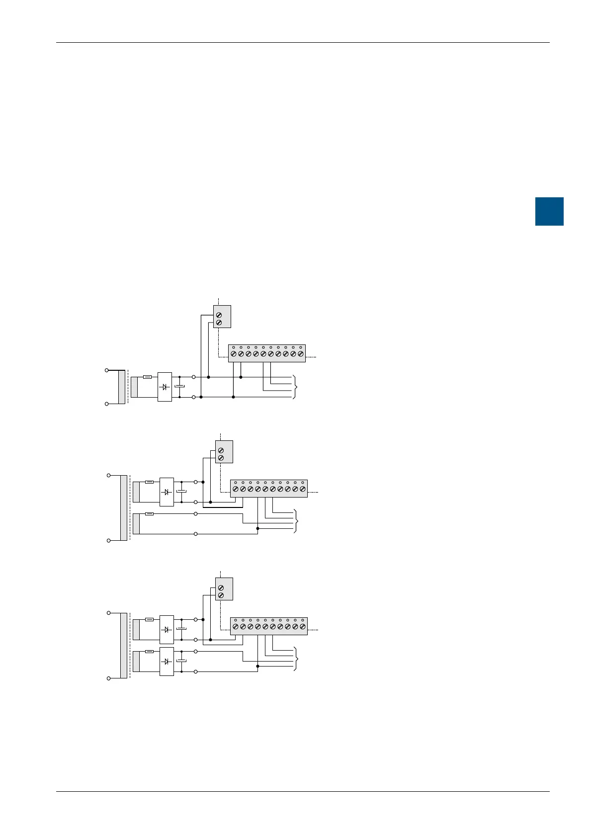
4.11.4 Supply possibilities
Common supply for controller and actuators
Tx1+24
VDC
GND GND GND A
Com
B
Com
Tx2Rx1 Rx2
012367
–
+
–
+
+
–
PCD2.T500
60 W
19 VAC
AC
AC
Fuse 4 A T
24 V
DC
Actuators
Separate supply of actuators with 24 VAC
–
+
+
–
Tx1+24
VDC
GND GND GND A
Com
B
Com
Tx2Rx1 Rx2
01237
–
+
+
–
PCD2.T500
AC
60 W
24 VAC
24 VDC
Actuators
Fuse 4 A T
Fuse 4 A T
19 V
AC
AC
AC
Individual DC supply for controller and actuators
–
+
+
–
Tx1+24
VDC
GND GND GND A
Com
B
Com
Tx2Rx1 Rx2
01237
–
+
–
+
+
–
PCD2.T500
24 VDC
Actuators
AC
60 W
19 VAC
AC
AC
Fuse 4 A T
Fuse 4 A T
19 V
AC
AC
AC