Saia-Burgess Controls AG
Manual Manual PCD 1 / PCD 2 Series │ Document 26 / 737 EN22 │ 2013-11-26
CPUs and expansion housings
3-34
PinCongurationPCD2
3
3.13 PinCongurationPCD2
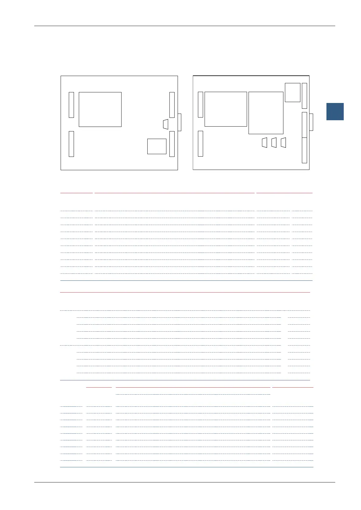
Situation of sockets and screw terminal blocks on PCD2
Supply/WD
Port #0/#6,
RS-485
Optional serial data ports on socket A, Port #1, Screw terminal block
Interrupt/counter
(On board)
Pin
20..29
Signal Pin
10..19
RS-485
PCD7.
F110
RS-422
PCD7.
F110
RS-232
PCD7.
F120
TTY/20 mA
PCD7.
F130
RS-485*
PCD7.
F150
MP-Bus
PCD7.
F180
Pin
0..9
Signal PCD2.
M1x0 M480
20 +24V 10 PGND PGND PGND PGND PGND PGND 0 INA1 IN0
21 +24V 11 RX-TX TX TXD TS RX-TX MP 1 INB1 IN1
22 +24V 12 /RX-/TX /TX RXD RS /RX-/TX ‚MFT‘ 2 INA2 IN2
23 PGND 13 – RX RTS TA – ‚IN‘ 3 INB2 IN3
24 PGND 14 – /RX CTS RA – ‚GND‘ 4 OUT1 OUT4
25 WD 15 PGND PGND PGND PGND PGND PGND 5 OUT2 OUT5
26 WD 16 – RTS DTR TC – 6 + +
27 PGND 17 – /RTS DSR RC – 7 L L
28 /D 18 – CTS RSV TG SGND 8 PGND PGND
29 D 19 – /CTS DCD RG – 9 PGND PGND
*
galvanically isolated
Optional serial data ports on sockets B/B1 and B2, Screw terminal block
Port
#
B/B1
Pin
B2
Pin
RS-232 +
RS-485
PCD2.F520/F530
RS-485,
PCD7.F772/F802
RS-232 + RS-422
PCD2.F520/F530
2xRS-232
PCD2.F522
RS-232 full
PCD2.F522
Port #2/4
30 40 PGND PGND PGND PGND
B1=Port #2 or B2=Port #4
PGND
31 41 TXD RX - TX TXD TXD TXD
32 42 RXD /RX - /TX RXD RXD RXD
33 43 RTS — RTS RTS RTS
34 44 CTS — CTS CTS CTS
Port #3/5
35 45 PGND — PGND PGND PGND
36 46 RX - TX — TX TXD DTR
37 47 /RX - /TX — /TX RXD DSR
38 48 — — RX RTS —
39 49 — — /RX CTS DCD
On board Optional serial ports on sockets B1 and B2,9poleD-Subconnector S-Net/MPI
D-Sub, Pin
Port #0
PGU
RS-232
Optional Ports #3 and #5 Port #10
1)
with PCD2.M480
only (instead of B2)
RS-232
PCD2.F522
RS-422
PCD2.F520/F530
RS-485
PCD2.F520/F530
Probus LonWorks
®
1 PGND PGND PGND PGND PGND PGND not used
2 RXD — — — — — M24V
3 TXD RXD /TX /RX - /TX RXD/TXD-P LONA RXD/TXD-P
2)
4 — — — — CNTR-P/RTS — CNTR-P
2)
5 GND RTS RX — GND LONGND DGND
2)
6 DSR CTS /RX — +5V — VP
2)
7 RTS — — — — — P24
8 CTS TXD TX RX - TX RXD/TXD-N LONB RXD/TXD-N
2)
9 +5V — — — — — not used
For details see manual 26/737
1)
Pro-S-IO:upto255PCD3.T76xarecontrollableW/OProbusmodules
2)
obligatory
39
30
29
20
PGU
#0
10
19
0
9
40
49
B2
#5/
S-Net/
MPI
#10
B1
#3
B1
Port #2 and #3
A
Port #1
B2
Port #4 and #5
PCD2.M170 / PCD2.M480
Port #0
RS-485
(with PCD2.M480
separate Port #6)
1) M480 with Pro-S-Net : up to 255 RIO head
stations PCD3.T76x are controllable WITHOUT
additional Probus communication module
39
30
29
20
0
9
10
19
PGU
Port #0
A
Port #1
B
PCD2.M150
Port #0
RS-485
Port #2 and #3
noisnapxe O/I