Saia-Burgess Controls AG
Manual Manual PCD 1 / PCD 2 Series │ Document 26 / 737 EN22 │ 2013-11-26
CPUs and expansion housings
3-28
Power supply and connection plan
3
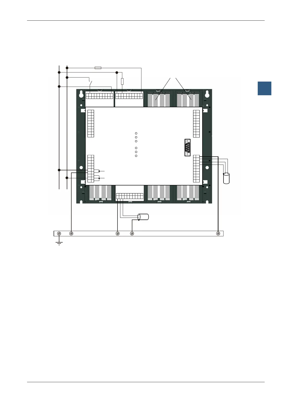
3.9.2 Earthing and connection plan
Ground wire plan with earthing bar
PGU
24 VDC
Battery
WD
Run
Halt
Error
CPU
Supply
1.5 mm
2
1.5 mm
2
Exxx Axxx
Wxxx
Earthing bar
_
_
_
_
+
+
+
Shielding and
grounding plate
1.5 mm
2
/ max. 25cm
InthebottompartofthePCD1/PCD2housingthereisashieldingandearthing
plate.Thisconstitutesthecommon,large-areagroundforallI/Omodulesandforthe
external power supply.
WhenamoduleispluggedinattheI/Olevel,thebladesonthisplateensurea
reliable multi-point contact to the relevant module.
The zero-potential (Minus pole) of the 24 V supply is connected to the Minus
terminal of the PCD1/PCD2 supply. This should be connected to the earthing bar
with the shortest possible wire (< 25 cm) of 1.5 mm
2
. The same applies to the Minus
connection to the F1xx or the interrupt terminal.
Any shielding of analogue signals or communication cables should also be brought to
the same earth potential, either via a Minus terminal or via the earthing bar.
All Minus connections are linked internally. For problem-free operation, these
connections should be reinforced externally with short wires of 1.5 mm
2
.