Saia-Burgess Controls AG
Manual Manual PCD 1 / PCD 2 Series │ Document 26 / 737 EN22 │ 2013-11-26
4
Communication interfaces
4-13
Serial interfaces on socket A
4.6 Plug-in interfaces modules: Socket A
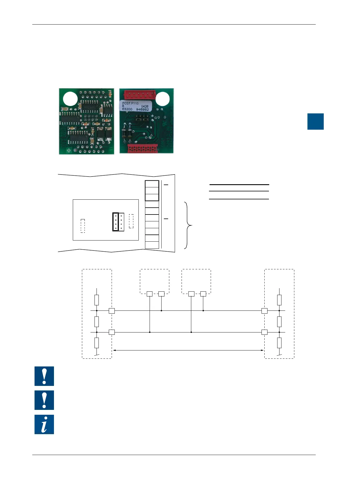
4.6.1 RS-485 / 422 with PCD7.F110, Port #1 (with PCD1.M110 hard-wired)
Connection for RS-485
PCD7.F110:
RS-422 with RTS / CTS or RS-485 electrically
connected, with line termination resistors
capable of activation, for socket A
10
11
12
J1
13
12
13
14
15
16
17
18
19 19
18
17
16
14
11
PGND
RX - TX
/RX - /TX
PGND
RX - TX
/RX - /TX
GND
OPEN
CLOSED
PCD7.F110
Socket A
not used
Bus-Cable
Scew terminal block
socket A
Choice of line termination resistors
+5 V +5 V
PCD1.M1xx
PCD2.Mxx0
PCD1.M1xx
PCD2.Mxx0
PCD1.M1xx
PCD2.Mxx0
/RX-/TX
RX-TX
12
/n
11
n /n n
/n
n
PCD1/2.Mxxx
Socket A
Pull up
330 Ohm
Pull down
330 Ohm
Segment lenght max. 1200 m
max. 32 stations
Termination
Resistor
150 Ohm
Not all manufacturers use the same connection conguration, so the data lines
sometimes need to be crossed.
At the rst and last stations, jumper J1 must be set to the “CLOSED” position.
At all other stations, jumper J1 must be set to “OPEN” (factory setting). The jumper
is on the connection side of the module.
For details, see manual 26 / 740 :
“Installation components for RS-485 networks”