Saia-Burgess Controls AG
Manual Manual PCD 1 / PCD 2 Series │ Document 26 / 737 EN22 │ 2013-11-26
4
Communication interfaces
4-14
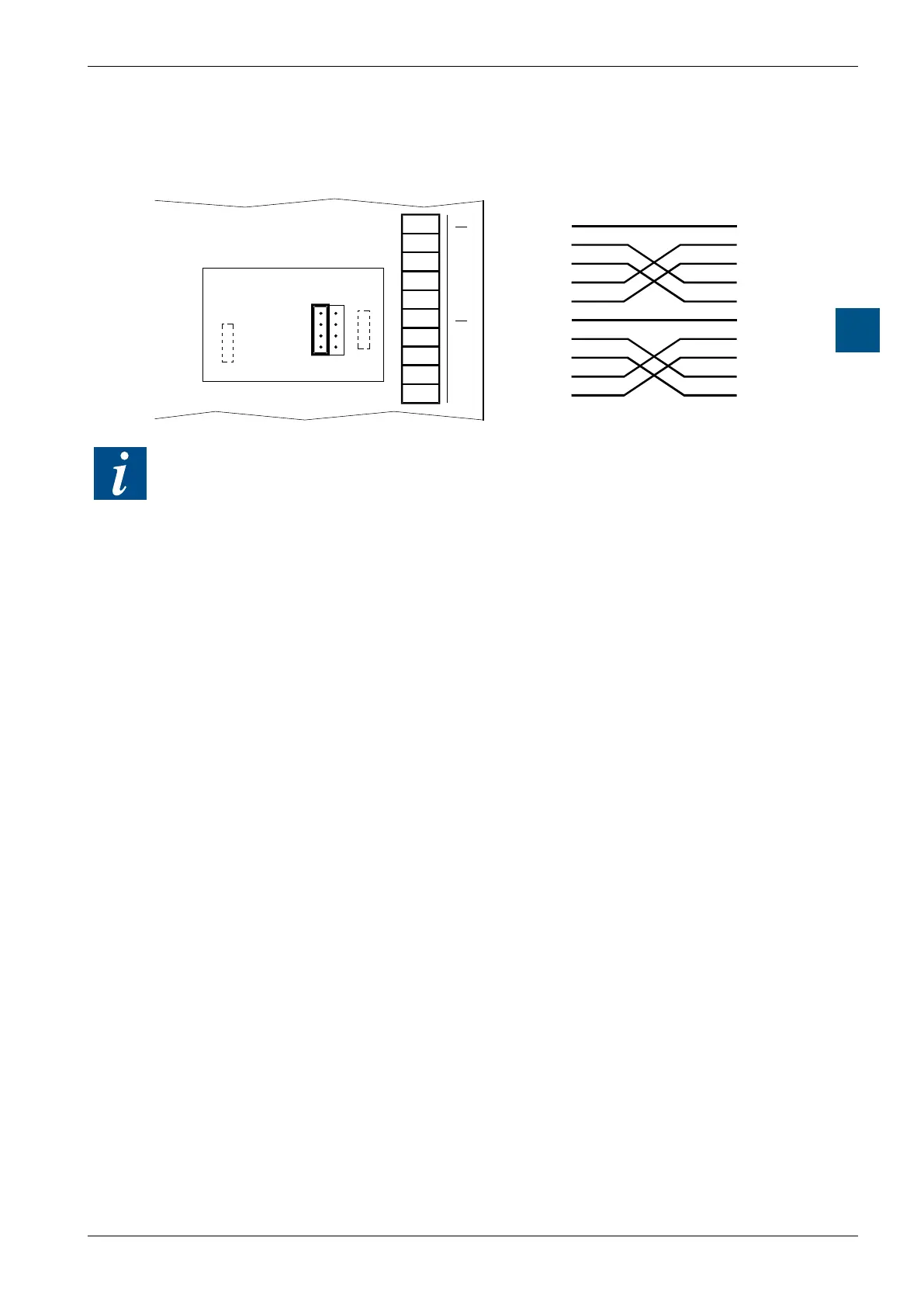
Serial interfaces on socket A
Connection for RS-422
10
11
12
13
14
15
16
17
18
19
J1
OPEN CLOSED
19
18
17
16
14
13
12
11
PCD7.F110
Socket A
PGND
TX
/TX
RX
/RX
PGND
RTS
/RTS
CTS
/CTS
PGND
TX
/TX
RX
/RX
SGND
RTS
/RTS
CTS
/CTS
Screw terminal block,
socket A
Cable
Peripheral
For RS-422, each pair of receive lines is terminated with a 150 Ω line termination
resistor. Jumper J1 must be left in the “OPEN” position (factory setting). The jumper
is on the connection side of the module.