Saia-Burgess Controls AG
Manual Manual PCD 1 / PCD 2 Series │ Document 26 / 737 EN22 │ 2013-11-26
5
Input/output (I/O) modules
5-41
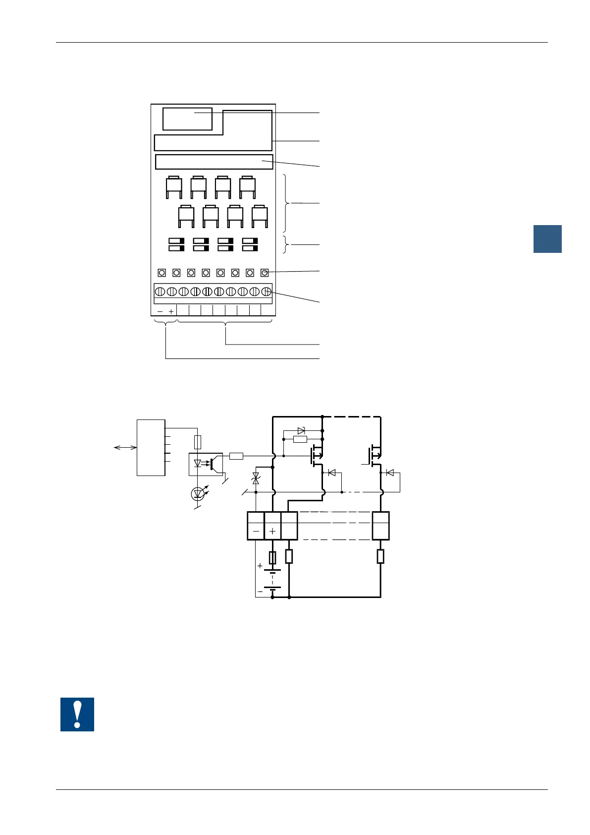
Digital output modules, electrically isolated
LEDs and connection terminals
Bus connector
Bus interface
Optocoupler
Output transistors (MOSFET)
Protective diodes
LEDs
Screw terminals
Outputs
Load supply 24 VDC
9 8 7 6 5 4 3 2 1 0
A0A1A2A3A4A5
A5A3A1
A4A2A0 A6
A7
A6A7
Output circuits and terminal designation
PCD Bus
18V
Output
transistors
(MOSFET)
Protective
diodes
Output conducting (set): LED on
Output disconnected (reset): LED off
Fuse: It is recommended that each module should be separately protected
with a fast-blow (S) 4 A fuse
Watchdog: This module can be used on all base addresses; there is no interaction with the
watchdog on the CPUs. For details, please refer to the “Watchdog” section, which describes
the correct use of the watchdog in conjunction with PCD2 components.