Saia-Burgess Controls AG
Manual Manual PCD 1 / PCD 2 Series │ Document 26 / 737 EN22 │ 2013-11-26
CPUs and expansion housings
3-13
CPU overview
3
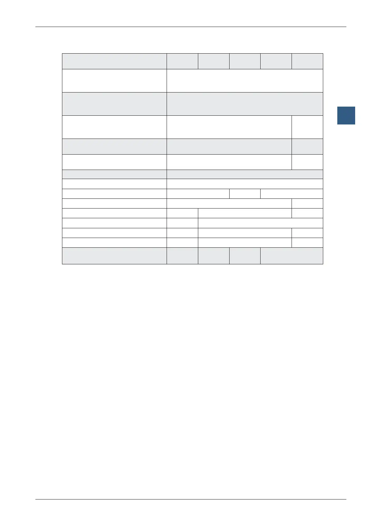
Differentiation of
PCD2 base units (ports)
M110 M120 M150 M170 M480
Programming interface PGUportD-Subsocket,9-pole
1)
(for PCD8.K111 programming cable)
PCD2.M480, also USB port
2)
Serial data port
Socket A
1 x
RS-232, RS-422/485 or TTY loop circuit 20mA,
plug-in (PCD7.F1xx modules)
Port#0(PGU)alsoavailableas
RS-485 interface (either RS-232 or
RS-485)
Additional serial data port RS-485
(Port 6, up to 115 kbps)
Pro-S-Netinterface
(up to 1.5 Mbps)
Field bus connections:
Serial-S-Bus (SBC S-Bus)
Ether-S-Bus(Ethernet-TCP/IP)
3)
Pro-S-Bus
ProbusFMS
4)
ProbusDPMaster
ProbusDPSlave
()
4)
LonWorks
®
4)
Socket for network and/or data port,
LEDdisplay,smallterminal
(1 × B)
5)6)
1 × B
6)
1 × B
6)
B1 and B2
6)7)8)
1) Can also be used as a serial data port, e.g. to connect a terminal; but this hampers comissioning and
troubleshooting with the debugger
2)TheUSBportistype“USB1.1SlaveDevice12Mbps”andcanonlybeusedforprogrammingandasanS-Bus
Slave,togetherwithcertainsoftwareproducts(Webconnect,ViSi-PLUSwithS-Driver)
3)EthernetTCP/IPavailableasaconguredsystemonthePCD2.M150:PCD2.M150F655.Ifinstalledlater,the
cover must be replaced (item-no. 4 104 7410 0)
4)ImplementationofLonWorksandProbusFMSistechnicallyfeasible,butnotplanned.ProbusDPSlavewith
ProS-Netportupto1.5Mbps;a12MbpssolutionwithPCD7.F770isnotfeasible
5)OnthePCD2.M110,SocketBcanonlybeusedtoattachthePCD7.D16xterminalkitandthePCD2.F510LED
display
6)WerecommendorderingthePCD7.D16xterminalkitmountedonthecontrol.Ifinstalledlater,theredviewingwin-
dowmustberemoved,andfourholesdrilledfortheterminalxingscrews(guideholesareprovidedontheinside
of the cover)
7)Notallcommunicationmodulescanbemountedonbothsockets;pleaserefertothesectionon“Communication”
8)ThePCD2.F510andPCD2.F530LEDdisplayscannotbeusedwiththePCD2.M170andPCD2.M480